Magnetic field sensor with increased field range

a magnetic field sensor and field range technology, applied in the field of magnetic field sensors, can solve the problems that the magnetic field measurement range of the broader magnetic field may not have the desired high sensitivity across the whole measurement range, and achieve the effect of increasing the magnetic field measurement range of the tmr magnetic field sensor and high measurement sensitivity

Active Publication Date: 2016-10-27
EVERSPIN TECHNOLOGIES
View PDF4 Cites 27 Cited by
  • Summary
  • Abstract
  • Description
  • Claims
  • Application Information

AI Technical Summary

Benefits of technology

[0007]Certain embodiments of the inventions provide for systems, devices, and methods to effectively increase magnetic field measurement range of a TMR magnetic field sensor and maintain high measurement sensitivity.
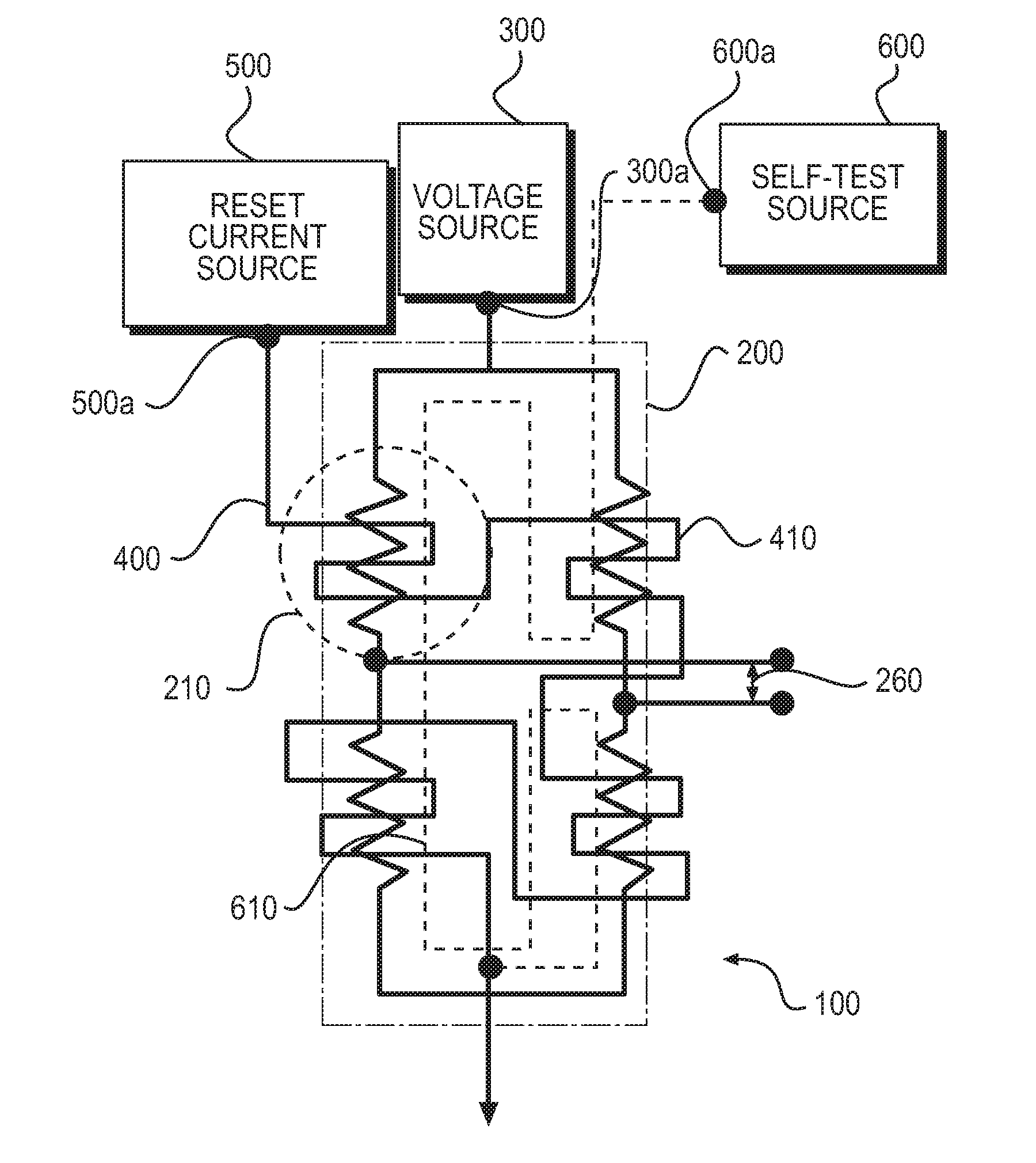
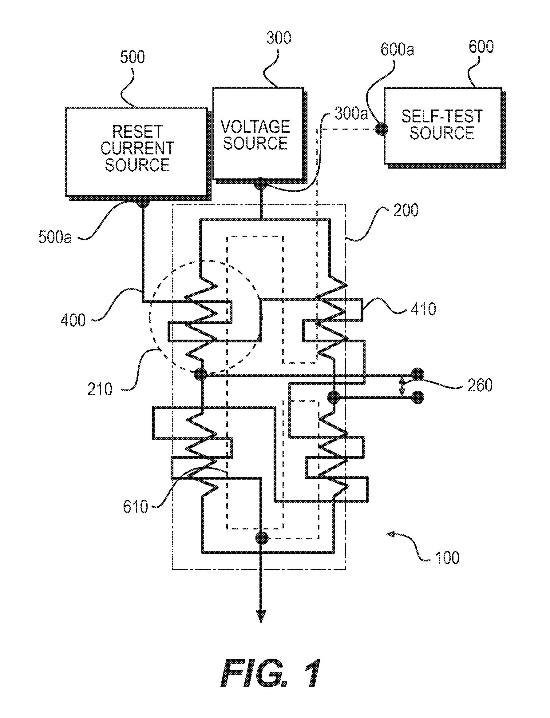
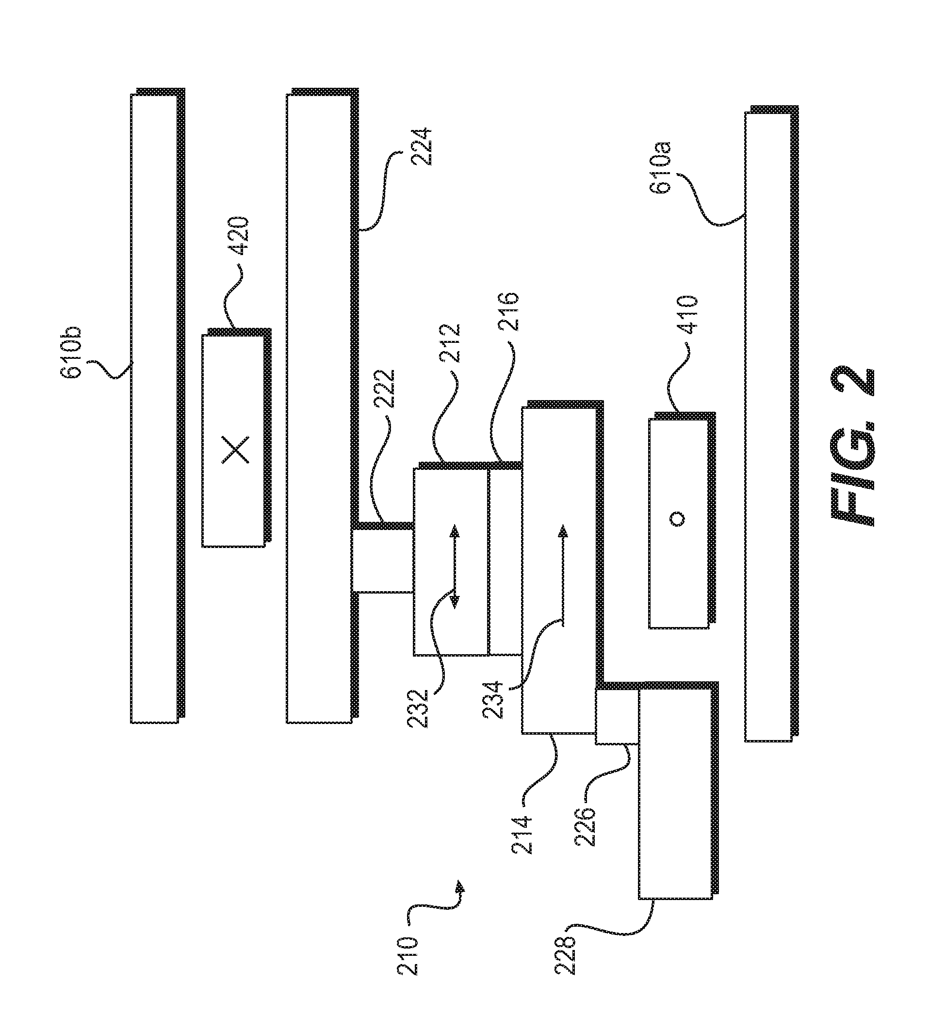
[0010]In certain embodiments, the magnetic field sensor may further comprise a second circuit that comprises a plurality of built-in current lines placed adjacent to the second ferromagnetic layer (e.g., the fixed layer) of each TMR element of the first bridge circuit. The current lines are serially or sequentially connected to a field source, and a periodic bipolar current pulse is applied to all of the current lines to form a magnetic 1 / f noise and an offset reduction within the TMR sensors. The periodic bipolar current pulse is applied only when the measured magnetic field (along one or more axes) is below a certain threshold. When the measured magnetic field is above the certain threshold, the built-in current lines are operated in a DC mode (i.e. without chopping). This allows for a low field high signal-to-noise ratio (SNR) operation, but avoids a possibility of over drive or inductive coupling to add noise at a output signal.

Problems solved by technology

On the other hand, a magnetic sensor with broader magnetic field measurement range may not have desired high sensitivity across the whole measurement range.

Method used


Image

  • Magnetic field sensor with increased field range
  • Magnetic field sensor with increased field range
  • Magnetic field sensor with increased field range

Examples


Embodiment Construction

[0026]In the following description, for the purpose of explanation, specific details are set forth in order to provide an understanding of the present inventions. The present inventions may, however, be practiced without some or all of these details. The embodiments of the present inventions described below may be incorporated into a number of different electrical components, circuits, devices, and systems. Structures and devices shown in block diagram are illustrative of exemplary embodiments of the present inventions and are not to be used as a pretext by which to obscure broad teachings of the present inventions. Connections between components within the figures are not intended to be limited to direct connections. Rather, connections between components may be modified, re-formatted, rerouted, or otherwise changed by intermediary components.

[0027]When the specification makes reference to “one embodiment” or to “an embodiment”, it is intended to mean that a particular feature, str...


PUM


Abstract

In one embodiment, a TMR field sensor utilizes existing one or more self-test current lines in a configuration to extend magnetic field measurement range without sacrificing measurement sensitivity. The self-test current lines are energized to facilitate magnetic field measurement when the measured magnetic field reaches a threshold. The magnetic field created by self-test coil opposes an external magnetic field being measured to keep the net magnetic field within a desired range where the magnetic field sensor has linear output and desired sensitivity.

Description

CROSS REFERENCE TO RELATED APPLICATIONS[0001]This application claims the benefit of priority to U.S. Provisional Application No. 62 / 153,066, filed Apr. 27, 2015, the entire contents of which is herein incorporated by reference.TECHNICAL FIELD[0002]The present inventions relate generally to the field of magnetic field sensors and more particularly to methods of increasing field range of magnetic field sensors.BACKGROUND OF THE INVENTION[0003]Magnetic field sensors have been commonly used in various electronic devices, such as computers, laptops, media players, smart phones, etc. There are several techniques / devices that can be used for detecting a magnetic field. Tunneling Magnetoresistance (TMR) is a promising magnetic sensing technology for handset applications due to its advantages in sensitivity, power, and process cost compared with other magnetic sensors. Another closely related technology in magnetic field sensing is Giant Magnetoresistance (GMR).[0004]A TMR element is compose...

Claims


Application Information

Patent Timeline
Patent Type & Authority Applications(United States)
IPC IPC(8): G01R33/09G01R17/10G01R33/00
CPCG01R33/098G01R33/093G01R17/10G01R33/0011G01R33/096
Inventor MOHAN, ANURAAGMATHER, PHILLIP G.
Owner EVERSPIN TECHNOLOGIES
Why Eureka
Try Eureka