Bilateral misalignment differential confocal detection method and device for free-form curve topography

A differential confocal and detection method technology, applied in the direction of measuring devices, optical devices, instruments, etc., can solve the problem of insufficient measurement accuracy, limit the measurement accuracy of free-form surface profiles, and cannot overcome the characteristics of sample surface roughness, undulation, and inclination. Differences and other issues to achieve the effect of improving detection accuracy and speed, and improving accuracy

Active Publication Date: 2018-07-10
BEIJING INSTITUTE OF TECHNOLOGYGY
View PDF10 Cites 27 Cited by
  • Summary
  • Abstract
  • Description
  • Claims
  • Application Information

AI Technical Summary

Problems solved by technology

[0006] To sum up, the existing measurement methods mainly have insufficient measurement accuracy, which cannot overcome the influence of sample surface roughness, undulation, inclination and other characteristic differences, which is the main bottleneck that currently limits the measurement accuracy of free-form surface contours.

Method used


Image

  • Bilateral misalignment differential confocal detection method and device for free-form curve topography
  • Bilateral misalignment differential confocal detection method and device for free-form curve topography
  • Bilateral misalignment differential confocal detection method and device for free-form curve topography

Examples


Embodiment 1

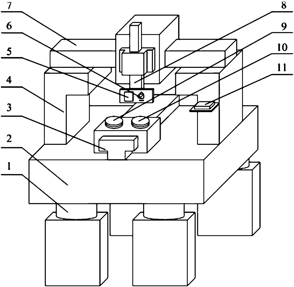
[0034] Such as figure 1 and figure 2 As shown, the device of the present invention includes: active air-floating vibration-isolation spring, air-floating vibration-isolation base, X-direction air-floating guide rail, gantry frame, bilateral misalignment laser differential confocal fixed-focus trigger measurement system, laser interference displacement measurement mirror Group, Y-direction air bearing guide rail, Z-direction air bearing guide rail, free-form surface sample attitude adjustment device, reference flat crystal attitude adjustment device, laser interferometer;

[0035] The nano-precision detection method of free-form surface morphology, the detection steps are as follows:

[0036] Step 1: Place the high-precision flat crystal on the free-form surface sample attitude adjustment device 9 and the reference flat crystal attitude adjustment device 10 respectively, and measure the distance between the laser interferometer mirror group 6 and the high-precision flat cryst...

Embodiment 2

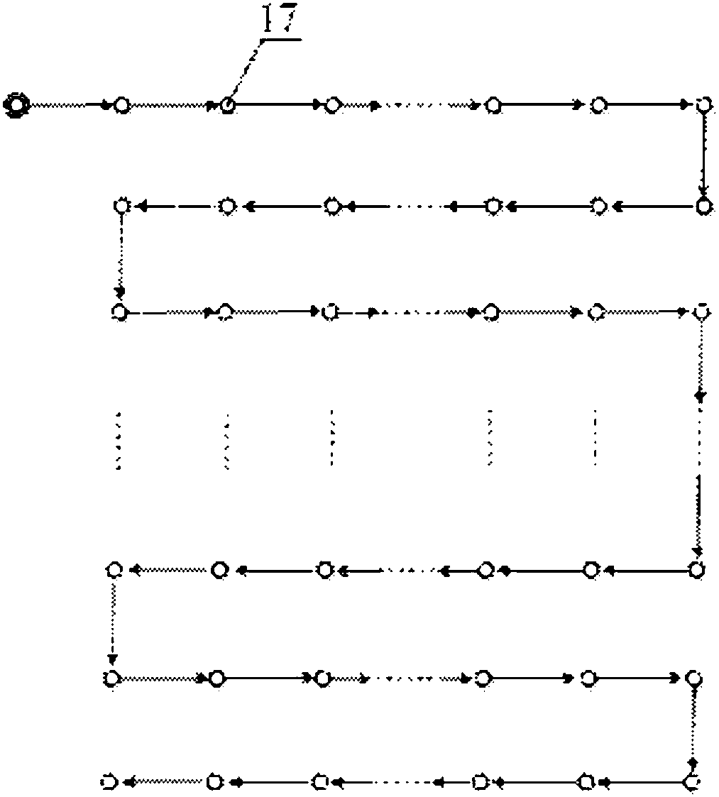
[0042] Such as figure 1 , figure 2 and image 3 As shown, the free-form surface morphology nano-precision detection method, the detection steps are as follows:

[0043] Step 1: Place the high-precision flat crystal on the free-form surface sample attitude adjustment device 9 and the reference flat crystal attitude adjustment device 10 respectively, and measure the distance between the laser interferometer mirror group 6 and the high-precision flat crystal through the laser interferometer 11 , adjust the attitudes of the free-form surface sample attitude adjustment device 9 and the reference flat crystal attitude adjustment device 10 to ensure that they are perpendicular to the Z-direction air bearing guide rail 8;

[0044] Step 2: Place the free-form surface sample to be tested and the high-precision flat flat crystal on the free-form surface sample attitude adjustment device 9 and the reference flat crystal attitude adjustment device 10 respectively, and use the Z-directio...


PUM


Abstract

The invention belongs to the technical field of optical precision detection, and relates to a bilateral misalignment differential confocal detection method and device for the free-form curve topography, which can be used for nano-precision detection of the free-form curve topography. The device comprises an active air floating vibration isolation spring, an air floating vibration isolation base, an X-direction air floating guide rail, a gantry, a bilateral misalignment laser confocal fixed-focus trigger measurement system, a laser interference displacement measuring mirror group, a Y-directionair floating guide rail, a Z-direction air floating guide rail, a free-form surface sample attitude adjustment device, a reference flat-crystal attitude adjustment device and a laser interferometer.By the way of contour measurement of a gantry structure coordinate measuring machine (CMM), in combination with the high-precision planar flat crystal as a reference reflecting mirror, the influence of the straightness of the X-direction and Y-direction air floating guide rails on the high-precision detection of the surface contour of the free-form surface is reduced, so that the 21 errors of theCMM are reduced. A spherical air floating table with a three-point support structure is used to adjust the attitude of a free-form surface part to be tested, and the high-precision detection of the contour of the free-form surface part is realized.

Description

technical field [0001] The invention belongs to the technical field of optical precision detection, and relates to a high-precision detection method and device for free-form surface topography, which can be used for nano-precision detection of free-form surface topography in precision optical systems. technical background [0002] The free-form surface element has the largest degree of freedom in surface morphology, and it is easy to eliminate aberrations in the imaging system. It can greatly improve the imaging quality and resolution of the measurement optical system, and improve the performance of weapons and equipment; use the free-form surface optical system to replace the previous optical system composed of plane, spherical mirror, coaxial quadric mirror, etc. to improve Imaging quality, reducing the volume and weight of the system, and then solving the problems of imaging accuracy, portability and reliability have become an important trend in the development of optical...

Claims


Application Information

Patent Timeline
Patent Type & Authority Applications(China)
IPC IPC(8): G01B11/24
CPCG01B11/2441
Inventor 赵维谦邱丽荣唐颖奇
Owner BEIJING INSTITUTE OF TECHNOLOGYGY
Why Eureka
Try Eureka