Ultrasonic automatic detection device and cable internal damage detection method

An automatic detection device, ultrasonic detection technology, applied in measuring devices, using ultrasonic/sonic/infrasonic waves, using sound waves/ultrasonic/infrasonic waves to analyze solids, etc. Problems such as high manual operation intensity can achieve the effect of strong load capacity, reduced moving speed and high driving efficiency

Active Publication Date: 2021-08-13
HANGZHOU DIANZI UNIV
View PDF12 Cites 0 Cited by
  • Summary
  • Abstract
  • Description
  • Claims
  • Application Information

AI Technical Summary

Problems solved by technology

For unstructured objects to be inspected, the detection effect is also poor. This is because the ultrasonic probe does not have a flexible matching characteristic with the structure, resulting in scattered ultrasonic signal emission, and does not have the ability to concentrate signals on the area to be inspected.
In addition, traditional ultrasonic testing usually requires manual operation, which is labor-intensive

Method used


Image

  • Ultrasonic automatic detection device and cable internal damage detection method
  • Ultrasonic automatic detection device and cable internal damage detection method
  • Ultrasonic automatic detection device and cable internal damage detection method

Examples


Embodiment 1

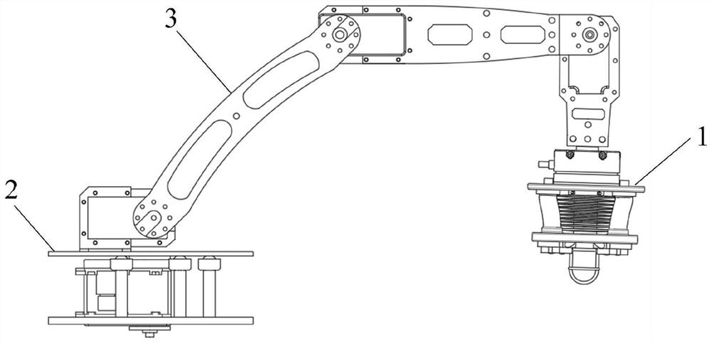
[0034] like figure 1 As shown, an ultrasonic automatic detection device includes an ultrasonic detection module 1 , a rotary base 2 and a mechanical arm moving device 3 . The rotary base 2 is installed on the fixed platform. The moving device 3 of the mechanical arm is installed on the rotary base 2 . The ultrasonic detection module 1 is installed at the end of the mechanical arm moving device 3 .

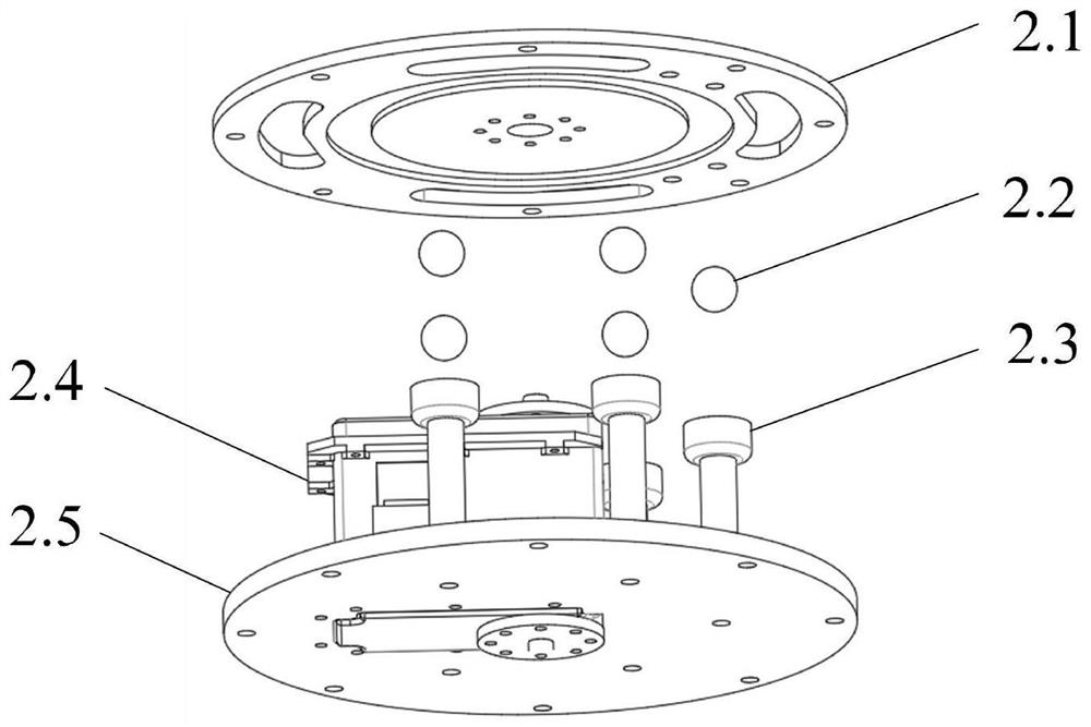
[0035] like figure 2 As shown, the slewing base 2 includes an upper support plate 2.1, a ball 2.2, a steering support rod 2.3, a rotating steering gear 2.4 and a lower support plate 2.5. The lower support plate 2.5 is fixed on the fixed platform. The rotary steering gear 2.4 is fixed on the center position of the lower support plate 2.5 top surface. The lower support plate 2.5 is fixed with five steering support rods 2.3 vertically arranged and evenly distributed along the circumferential direction of the axis of the lower support plate 2.5. The top of the steering support r...

Embodiment 2

[0048] The difference between this embodiment and Embodiment 1 is that the present invention can be applied to the non-destructive testing of other flexible structures, and the ultrasonic transceiver 1.7 can be replaced according to the change of the outer contour of the object to be tested, so that the probe of the ultrasonic transceiver 1.7 can be more fitted to the measured object Flexible structured surface.


PUM


Abstract

The invention discloses an ultrasonic automatic detection device and a cable internal damage detection method. The detection device comprises an ultrasonic detection module and a mechanical arm moving device. The ultrasonic detection module comprises a pressure sensor, a first connecting disc, hydraulic telescopic pipes, a second connecting disc, distance measuring sensors and an ultrasonic transceiver. The first connecting disc is installed at the tail end of the mechanical arm moving device through the pressure sensor. The second connecting disc and the first connecting disc are connected through a plurality of hydraulic telescopic pipes. The hydraulic telescopic pipes are evenly distributed in the circumferential direction of the axis of the first connecting disc. A spiral limiting layer is arranged in the side wall of each hydraulic telescopic pipe. The hydraulic telescopic pipes are connected with a hydraulic source and can independently control liquid filling and discharging. The ultrasonic transceiver and a plurality of distance measuring sensors are installed on the outer side of the second connecting disc. The distance measuring sensors are evenly distributed in the circumferential direction of the ultrasonic transceiver. According to the invention, the automatic detection of a flexible structure can be realized, the operation of manually holding the ultrasonic detection device is not needed, and the working efficiency is effectively improved.

Description

technical field [0001] The invention belongs to the technical field of ultrasonic detection, and in particular relates to an automatic ultrasonic detection device and a method for detecting internal damage of cables. Background technique [0002] Ultrasound generally refers to high-frequency sound waves with a frequency greater than 20kHz, and can propagate continuously in the medium, with relatively strong reflection ability and very easy to obtain signals. These advantages of ultrasound make it often used in non-destructive testing. Usually, the frequency range used in ultrasonic testing is 0.2-25 MHz. Traditional ultrasonic testing is usually used for objects with a definite structure. If the shape, structure, size, etc. of the object change, the corresponding ultrasonic probe needs to be replaced. For unstructured objects to be inspected, the detection effect is also poor. This is because the ultrasonic probe does not have the characteristics of flexible matching with ...

Claims


Application Information

Patent Timeline
Patent Type & Authority Applications(China)
IPC IPC(8): G01N29/04G01N29/22G01S15/08G01L5/00G01B17/00G01B17/06
CPCG01N29/04G01N29/225G01S15/08G01L5/00G01B17/00G01B17/06
Inventor 许明王冠
Owner HANGZHOU DIANZI UNIV
Why Eureka
Try Eureka