Bypass turbomachine with artificial variation of its throat section

a turbomachine and throat section technology, applied in the direction of machines/engines, marine propulsion, vessel construction, etc., can solve the problems of relatively expensive fabrication of variable section nozzles and difficult implementation of turbomachine nozzles for civilian applications

Active Publication Date: 2011-05-31
SN DETUDE & DE CONSTR DE MOTEURS DAVIATION S N E C M A
View PDF22 Cites 16 Cited by
  • Summary
  • Abstract
  • Description
  • Claims
  • Application Information

AI Technical Summary

Benefits of technology

[0006]The main object of the present invention is thus to mitigate such drawbacks by proposing a bypass turbomachine having a nozzle that is geometrically fixed but presenting throat section that can nevertheless be varied artificially depending on the operating speeds.
[0008]Thus, by injecting air downstream from the nozzle throat section, it is possible to increase artificially the rate at which air passes through said section, which amounts to opening the section of the nozzle while using the same geometrical section for the throat. This artificial variation in the throat section presents the advantages of requiring few parts, of being easy to install, and of being compatible with existing turbomachines. Another advantage lies in the possibility of improving noise levels.
[0010]Thus, by injecting air into the vicinity of the throat section of the nozzle, it is possible to decrease artificially the rate at which air passes through said section, which amounts to closing the nozzle throat section while using the same geometrical section for the throat.

Problems solved by technology

Unfortunately, those techniques are difficult to implement on the nozzles of turbomachines for civilian applications.
This is due in particular to constraints associated with installing the nacelle relative to the wing of the airplane, to ground clearance, and to the thicknesses and shapes of the trailing edges of the nacelle.
Furthermore, such variable section nozzles are relatively expensive to fabricate.

Method used


Image

  • Bypass turbomachine with artificial variation of its throat section
  • Bypass turbomachine with artificial variation of its throat section
  • Bypass turbomachine with artificial variation of its throat section

Examples


Embodiment Construction

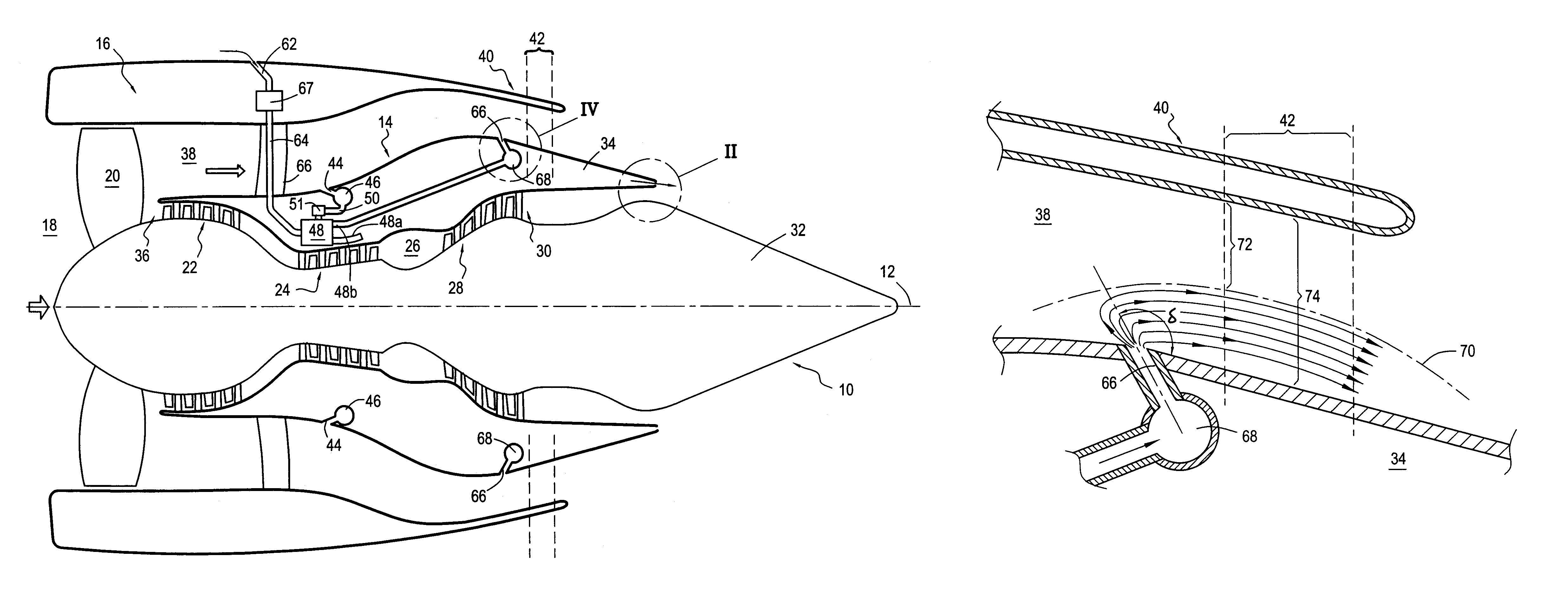
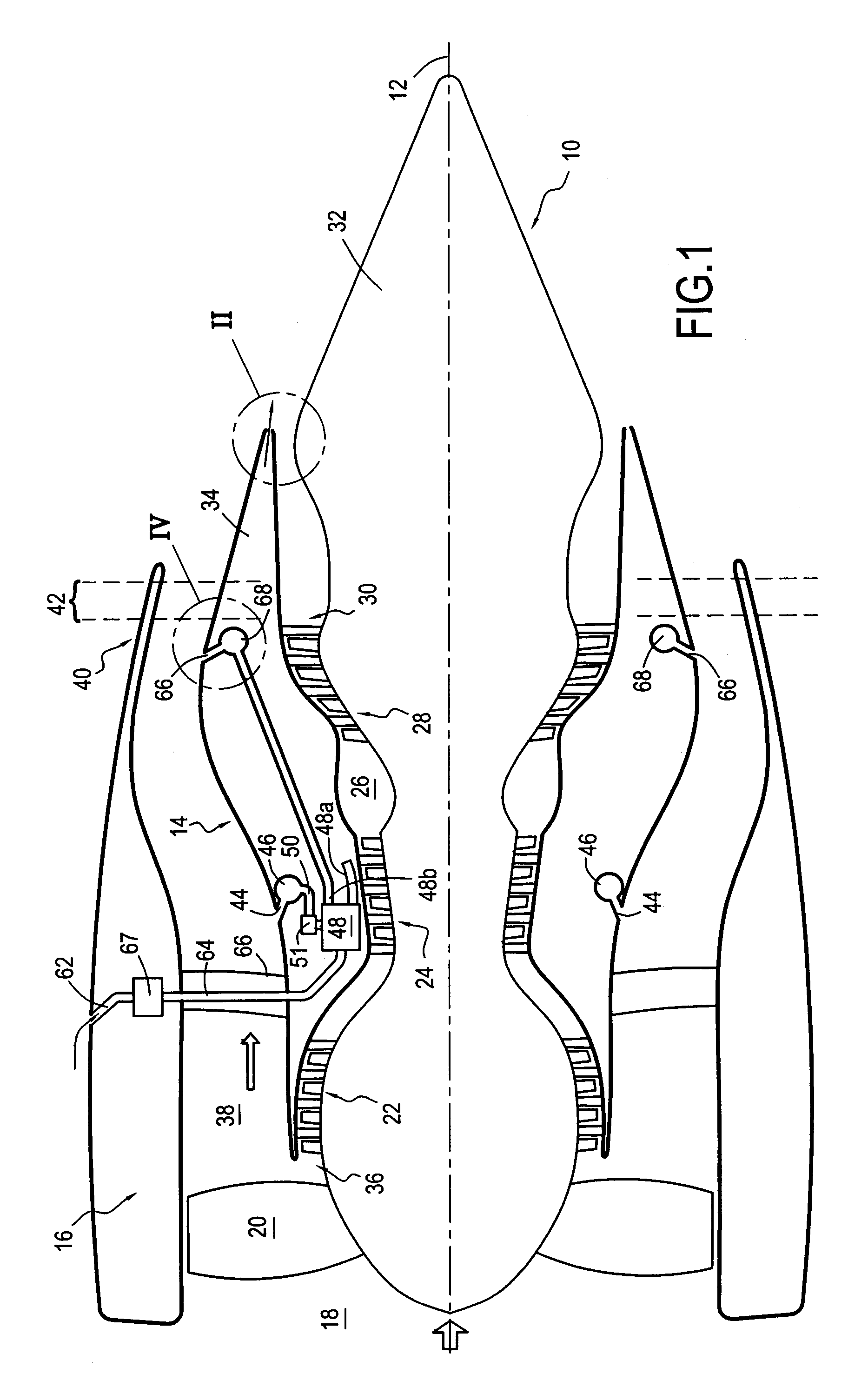
[0026]FIG. 1 is a highly diagrammatic longitudinal section view of a bypass turbomachine 10 of the invention. It possesses a longitudinal axis 12 and is made up of a gas turbine engine 14 and an annular nacelle 16 centered on the axis 12 and disposed concentrically around the engine.

[0027]From upstream to downstream in the flow direction of a stream of air passing through the turbomachine, the engine 14 comprises an air inlet 18, a fan 20, a low-pressure compressor 22, a high-pressure compressor 24, a combustion chamber 26, a high-pressure turbine 28, and a low-pressure turbine 30, each of these elements being disposed on the longitudinal axis 12.

[0028]The gas turbine engine also comprises a central body 32 centered on the longitudinal axis 12 of the turbomachine and a primary cowl 34 likewise centered on the axis 12 and surrounding the central body so as to form downstream from the fan 20 an annular channel 36 referred to as the primary channel and through which there flows a hot s...


PUM


Abstract

The invention relates to a bypass turbomachine comprising a gas turbine engine provided with a fan disposed on a longitudinal axis of the turbomachine, and an annular nacelle surrounding the engine so as to define a cold stream flow channel, the nacelle having an upstream end surrounding the fan of the engine and a stationary downstream end forming a gas exhaust nozzle, the nozzle having a throat section that corresponds to its smallest cross-section. The turbomachine further comprises means for taking in air from the cold stream flow channel upstream from the nozzle throat section, and means for injecting the taken-in air downstream from the nozzle throat section so as to open the throat section artificially.

Description

BACKGROUND OF THE INVENTION[0001]The present invention relates to the general field of the gas exhaust nozzle fitted to bypass turbomachines, and it relates more particularly to a turbomachine having a stationary nozzle in which the throat section can nevertheless be varied artificially.[0002]A bypass turbomachine comprises in particular a gas turbine engine provided with a fan disposed on a longitudinal axis of the turbomachine, and with an annular nacelle centered on the longitudinal axis of the turbomachine and surrounding the engine, the nacelle having an upstream end surrounding the fan of the engine and a downstream end forming a nozzle for ejecting the gas coming from the turbomachine. The term “throat section” is used to designate the cross-section of the nozzle constituting its smallest cross-section along the entire length of the nozzle.[0003]It is known that by varying the throat section of the nozzle of a turbomachine, it is possible to control the flow rate through the ...

Claims


Application Information

Patent Timeline
Patent Type & Authority Patents(United States)
IPC IPC(8): F02K1/00F02K1/28
CPCF01D9/065F02K3/06F02K1/386F02K1/30
Inventor BEUTIN, ALBERT BRUNOLANDRE, ERIC
Owner SN DETUDE & DE CONSTR DE MOTEURS DAVIATION S N E C M A
Why Eureka
Try Eureka