Method for routing incoming and outgoing data in an NFC chipset

a technology of incoming and outgoing data and chipset, which is applied in the field of routing data in a chipset, can solve the problems of a certain number of practical problems, insufficient for one of the processors, and frames with long and complex header fields

Active Publication Date: 2011-06-07
VERIMATRIX INC
View PDF20 Cites 153 Cited by
  • Summary
  • Abstract
  • Description
  • Claims
  • Application Information

AI Technical Summary

Benefits of technology

[0024]Embodiments of the present invention provide a method enabling, in an NFC chipset, the recipient host processor of data received via a contactless data transmission channel to be determined, without necessarily having to analyze the content of the data.

Problems solved by technology

This poses a certain number of practical problems that will be understood with reference to FIGS. 3A and 3B.
It is therefore not sufficient for one of the processors HP1 or HP2 to simply send to the interface CLINT the data to be transmitted.
Classic HCI protocol provides data frames having long and complex header fields, requiring a considerable processing time before the data is are processed.
This is referred to as “overheading”, which means that excessively long frame headers overload the data streams and increase the data transmission time.
These large header fields further require large buffers and high processing capacity.
Additionally, when incoming data is received, the contactless data send / receive interface CLINT and the controller NFCC do not necessarily know which is the intended host processor of the data.
Indeed, the routing is an internal problem linked to the fact that several processors of a same chipset share the same contactless data send / receive interface.
It is therefore quite unlikely in the near future that a universal routing protocol will be integrated into devices that do not meet an NFC standard.
Therefore, during an authentication, such a reader does not know whether it is addressing a real contactless card or an NFC chipset in “card emulation” mode.
As a result, such a reader is not designed to send parameters enabling the application data it sends to be routed inside the chipset.

Method used


Image

  • Method for routing incoming and outgoing data in an NFC chipset
  • Method for routing incoming and outgoing data in an NFC chipset
  • Method for routing incoming and outgoing data in an NFC chipset

Examples


Embodiment Construction

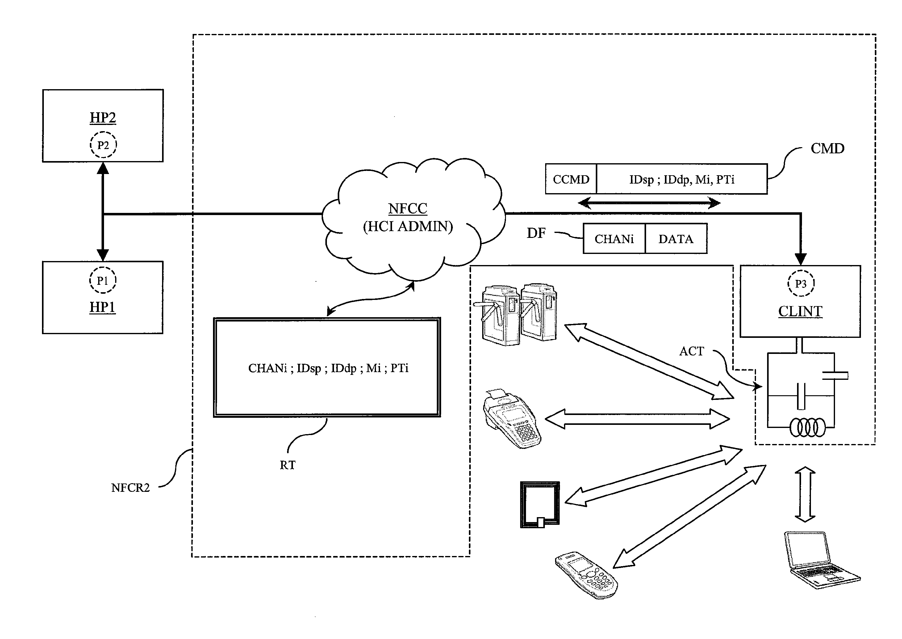
[0055]FIG. 4 schematically shows the implementation of the routing method according to a preferred embodiment of the present invention. The method is implemented in an NFC chipset comprising an NFC reader referenced “NFCR2” and host processors HP1, HP2 as described above. The reader NFCR2 comprises the same units as the reader NFCR1 described above, particularly a controller NFCC and a contactless data send / receive interface CLINT equipped with an antenna circuit ACT. For the sake of simplicity, it is assumed that the interface CLINT can only send or receive data according to three protocols PTi, i.e., the protocol PT1 (ISO 14443-A or “ISOA”), the protocol PT2 (ISO 14443-B or “ISOB”), and the protocol PT3 (ISO 15693 or “ISO15”). The interface CLINT further has the three abovementioned operating modes Mi, i.e., M1 (“reader” mode), M2 (“card emulation” mode), and M3 (“device” mode).

[0056]Source or destination points of a data stream in the chipset are designated P1 (point located in t...


PUM


Abstract

A method for routing data in a chipset comprising at least two host processors and one RFID-type contactless data send / receive interface configurable according to several operating modes and according to several contactless communication protocols includes routing, to at least one of the host processors, data received by the contactless data send / receive interface via a contactless data transmission channel. The method further includes determining a destination point of the data in a host processor using as criteria to determine the destination point the operating mode and the contactless communication protocol used by the contactless data send / receive interface to create the contactless data transmission channel through which the data are received.

Description

BACKGROUND OF THE INVENTION[0001]Embodiments of the present invention relate to a method for routing data in a chipset comprising at least one host processor and a Radio Frequency Identification (RFID)-type contactless data send / receive interface.[0002]Embodiments of the present invention also relate to a data send / receive circuit comprising an RFID-type contactless data send / receive interface, a controller, and at least one input / output port to link the data send / receive interface to a host processor.[0003]Embodiments of the present invention relate particularly to the production of a Near Field Communication (NFC) chipset.[0004]NFC technology is currently developed by an industrial consortium grouped under the name Forum NFC (http: / / www.nfc-forum.org). The NFC technology is derived from RFID technology and uses NFC readers having several operating modes, i.e., a “reader” Mode, a “card emulation” mode, and a “device” mode (also referred to as “device-to-device” mode). In the “reade...

Claims


Application Information

Patent Timeline
Patent Type & Authority Patents(United States)
IPC IPC(8): G06K19/06H04L45/74H04L45/60
CPCH04L45/54H04L45/00
Inventor CHARRAT, BRUNO
Owner VERIMATRIX INC
Why Eureka
Try Eureka