Support structures for planar insertion devices

a support structure and planar technology, applied in the direction of accelerators, magnetic bodies, electrical apparatus, etc., can solve the problems of complex devices capable of moving the magnet array of polarizing insertion devices

Inactive Publication Date: 2011-06-07
ADVANCED DESIGN CONSULTING USA
View PDF8 Cites 36 Cited by
  • Summary
  • Abstract
  • Description
  • Claims
  • Application Information

AI Technical Summary

Problems solved by technology

Polarizing insertion devices are more complex devices capable of moving the magnet arrays longitudinally as well as vertically and they see additional forces including repulsive vertical, and also transverse and longitudinal forces.
These trends challenge the existing mechanical support and drive systems configurations for the insertion devices.

Method used


Image

  • Support structures for planar insertion devices
  • Support structures for planar insertion devices
  • Support structures for planar insertion devices

Examples


Embodiment Construction

Orientation Terms Used

[0022]Longitudinal direction refers to a direction parallel to the theoretical centerline of the synchrotron or linear accelerator particle beam. For practical reasons, the particle beam generally runs horizontally. Transverse direction refers to a direction orthogonally transverse to the particle beam and also horizontal. The remaining orthogonal direction is vertical.

[0023]In describing rotations, roll means a rotation about a horizontal axis parallel to the particle beam. Pitch means rotation about a horizontal axis transverse to the particle beam. Yaw means a rotation about a vertical axis.

Planar Insertion Device Construction—Current Technology

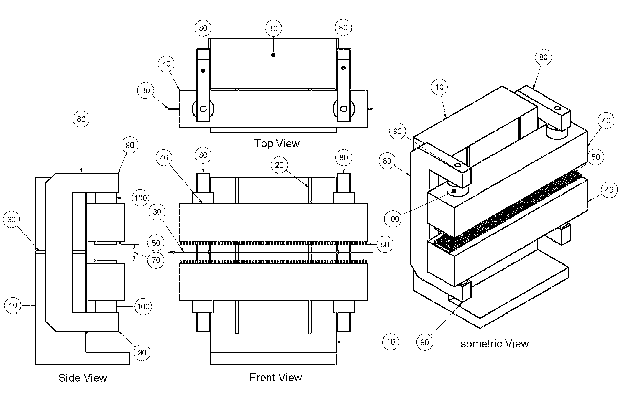
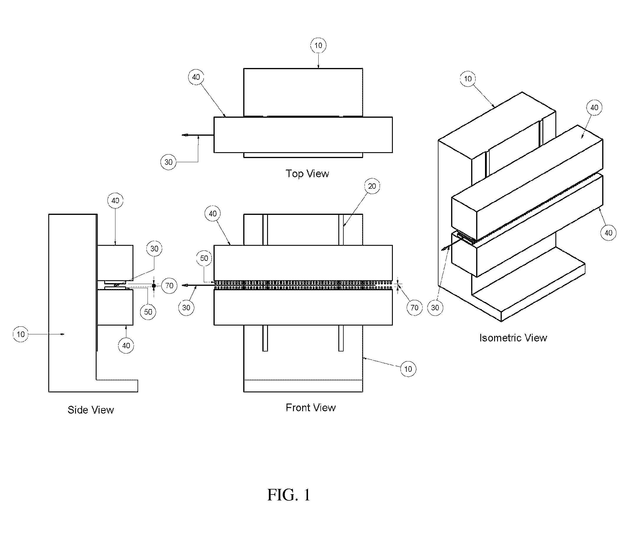
[0024]Referring now to FIG. 1, a planar insertion device according to currently practiced technology is shown, with an insertion device frame (10) affixed to the floor. The frame 10 holds linear guidance assemblies such as rails or ways (20), in a vertical orientation, allowing the girders (40) to move in the vertical...


PUM


Abstract

A planar insertion device and supporting structure for a planar insertion device for treating a synchrotron radiation beam includes a primary frame on which at least two secondary C-frames are mounted. An upper and a lower girders are mounted on the secondary C-frames forming a gap between girders and arranged substantially horizontally and parallel to each other and to the synchrotron radiation beam. Magnetic arrays rigidly mounted on the girders are facing each other and facing the gap between girders, with the synchrotron radiation beam passing between the magnetic arrays through the gap. The planar insertion device supporting structure prevents detrimental deformation reactions to variations of magnetic loadings with changes in the gap and subsequent geometrical misalignments.

Description

[0001]This application claims the benefit of U.S. Provisional Application No. 60 / 971,561, filed Sep. 11, 2007.TECHNICAL FIELD[0002]The invention relates to insertion devices for use with synchrotron radiation and more particularly to supporting structures for insertion devices, providing for reduced unwanted movements and deformations of the horizontal girders supporting magnet arrays treating a synchrotron particle beam.BACKGROUND[0003]Insertion devices (ID's) also known as undulators and wigglers are used in second and third generation synchrotrons and linear particle accelerators such as free electron laser facilities. Insertion devices are designed to hold and precisely position arrays of strong magnets in proximity to the particle beam and thereby produce brilliant x-rays that are used for a broad range of scientific experiments. There are specific tolerance requirements for magnet array positioning for each insertion device, depending on parameters of the particular synchrotro...

Claims


Application Information

Patent Timeline
Patent Type & Authority Patents(United States)
IPC IPC(8): H05H11/00H05H7/00
CPCH05H7/04H01F7/0273
Inventor WATERMAN, DAVID JOHN
Owner ADVANCED DESIGN CONSULTING USA
Why Eureka
Try Eureka