Proton accelerator complex for radio-isotopes and therapy

a proton beam and accelerator technology, applied in the field of proton beam accelerator complex, to achieve the effect of large energy reduction, less maintenance, and more reliabl

Inactive Publication Date: 2009-06-30
FOND PER ADROTERAPIA ONCOLOGICA TERA
View PDF6 Cites 49 Cited by
  • Summary
  • Abstract
  • Description
  • Claims
  • Application Information

AI Technical Summary

Benefits of technology

[0026]This is an important feature in the depth scanning of a tumour target since, as indicated in Table 4, cyclotrons and FFAGs produce beams of fixed energy and require the movement of absorbers to vary the penetration range in the body of the patient with a well established technique. On the other side PACRIT energy and intensity are adjusted in one millisecond and electronic controls are more reliable and require less maintenance than mechanical ones, a clear plus considering the many decades during which such a center has to run. Moreover the use of absorbers entails the production of secondary particles, mainly neutrons, which have to be shielded and can, if the energy reduction is large, induce dangerous radioactivity. From this point of view PACRIT is similar to a synchrotron, since the output energy and intensity of the machine can be varied without moving parts, with the added advantage that the adjustments require one millisecond instead of about one second. Furthermore it is worth remarking that in a cyclotron the range variation of the 200-250 MeV protons produced requires not only absorbers but also an ‘Energy Selection System’ (ESS) which is as long as the linac of PACRIT, so that the area needed for the buildings is not larger in spite of the dual use of the cyclotron.
[0027]A further advantage of the time structure of the beam is apparent when considering the spot scanning technique developed at the Paul Scherrer Institute in Villigen (Switzerland), where the spot is moved transversally to the beam in about two milliseconds: the time separating two succe

Problems solved by technology

The only limitations are due to the needed investments and the dimension

Method used


Image

  • Proton accelerator complex for radio-isotopes and therapy
  • Proton accelerator complex for radio-isotopes and therapy

Examples


Embodiment Construction

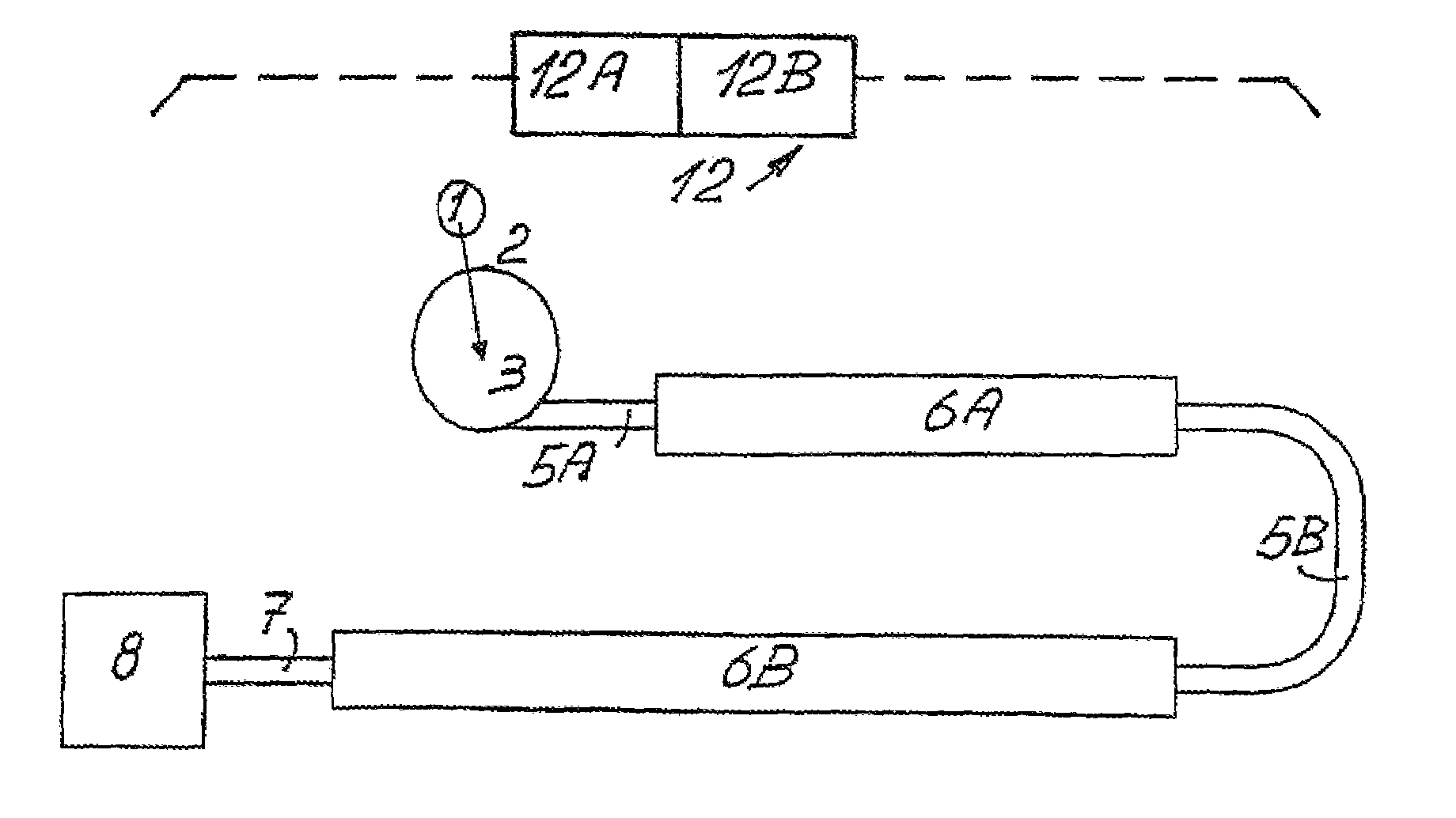
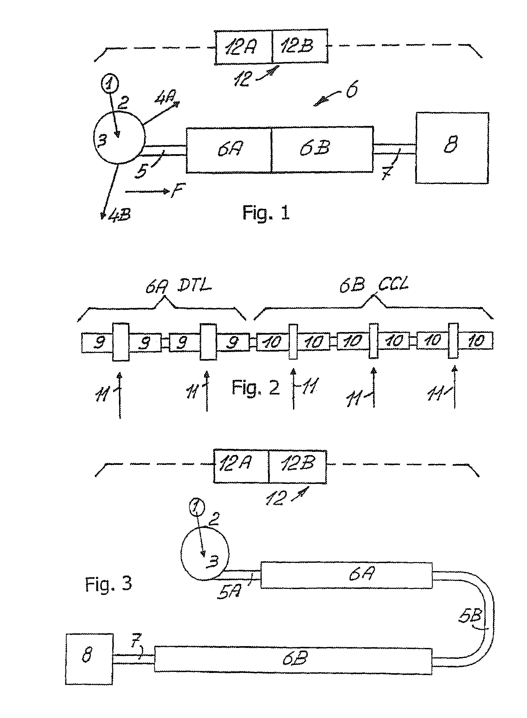
[0040]The components of the proton accelerator complex for radioisotope production and proton therapy, shown in FIGS. 1-3, are the folowing:[0041]1. proton source;[0042]2. Low Energy Beam Transport channel (LEBT)[0043]3. cyclotron;[0044]4A and AB two of the many possible beam lines for the production of radioisotopes on internal and / or external targets;[0045]5. Medium Energy Beam Transport channel (MEBT)[0046]5A low-medium energy channel[0047]5B medium-high energy channel;[0048]6. high-frequency linac, with frequency typically larger than 1 GHz;[0049]6A modular accelerating section of the Drift Tube Linac structure (DTL) of linac 6 with a number of modules depending on the application;[0050]6B modular accelerating section of the Cavity Coupled Linac structure (CCL) of linac 6 with a number of modules depending on the application;[0051]7. High Energy Beam Transport channel (HEBT);[0052]8. area where the therapeutical beam is used to irradiate patients with fixed and, if desired, rota...


PUM


Abstract

A complex of proton accelerators, includes the following functionally interconnected components: a proton source, a cyclotron, at least one target, located either internally or externally to the cyclotron, a medium energy beam transport magnetic channel, a radiofrequency linear accelerator, a high energy beam transport channel towards an area dedicated to the irradiation of tumors with proton beams, as well as a modular system for supplying radio frequency power capable of feeding, independently two or more accelerating modules of the linac. An integrated computerized system controls the complex of accelerators so to carry out, either in alternation or simultaneously, both the production of radioisotopes—for medical, industrial and therapeutical purposes—and the therapeutical irradiation of, even deep seated tumors. The complex of accelerators produces proton beams which, applying the recently developed ‘spot scanning’ technique, are more suited for the tumor irradiation than the ones produced by cyclotrons and synchrotrons.

Description

FIELD OF THE INVENTION[0001]This invention refers to a complex of accelerators of proton beams, to a method and the use thereof. Referring to its functionality the proposed complex of accelerators is called PACRIT (Proton Accelerator Complex for Radio-Isotopes and Therapy).BACKGROUND OF THE INVENTION[0002]It is well known that the use of radiopharmaceuticals injected in the body of the patient is an essential tool in medical diagnostic and in particular in the diagnostic of tumours. Gamma scintigraphy, also named Single Photon Emission Tomography (SPET or SPECT), is the most common technique. But, in the past fifteen years, Positron Emission Tomography (PET) has spread quickly also in association with the quantitative observation of the morphology of internal organs allowed by Computerized Tomography (CT). The future of tumor diagnostic is in the use of combined devices as CT / PET and also MRI / PET (MRI=Magnetic Resonance Imaging).[0003]These widespread diagnostic methods employ radio...

Claims


Application Information

Patent Timeline
IPC IPC(8): H05H9/00
CPCH05H6/00A61N2005/1087
Inventor AMALDI, UGO
Owner FOND PER ADROTERAPIA ONCOLOGICA TERA
Why Eureka
Try Eureka