Charged particle extraction apparatus and method of use thereof

a technology of charged particles and extraction apparatuses, which is applied in the direction of beam deviation/focusing, therapy, instruments, etc., can solve the problems of reducing the ability to repair damaged dna, affecting the treatment effect, and affecting the ability of patients to recover damaged dna,

Active Publication Date: 2013-03-19
BALAKIN ANDREY VLADIMIROVICH +1
View PDF274 Cites 51 Cited by
  • Summary
  • Abstract
  • Description
  • Claims
  • Application Information

AI Technical Summary

Problems solved by technology

These particles damage the DNA of cells, ultimately causing their death.
Cancerous cells, because of their high rate of division and their reduced ability to repair damaged DNA, are particularly vulnerable to attack on their DNA.

Method used


Image

  • Charged particle extraction apparatus and method of use thereof
  • Charged particle extraction apparatus and method of use thereof
  • Charged particle extraction apparatus and method of use thereof

Examples


Embodiment Construction

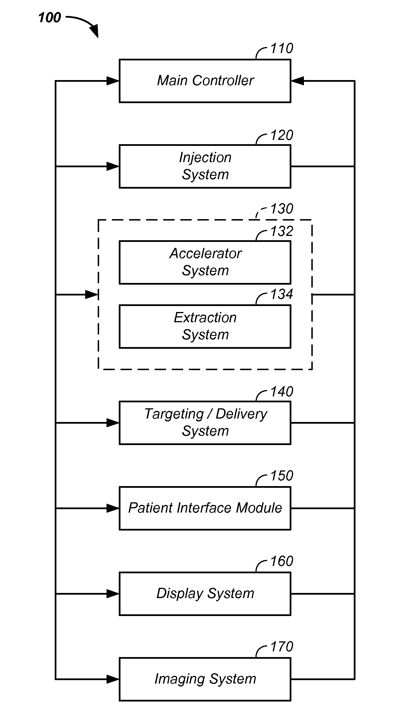
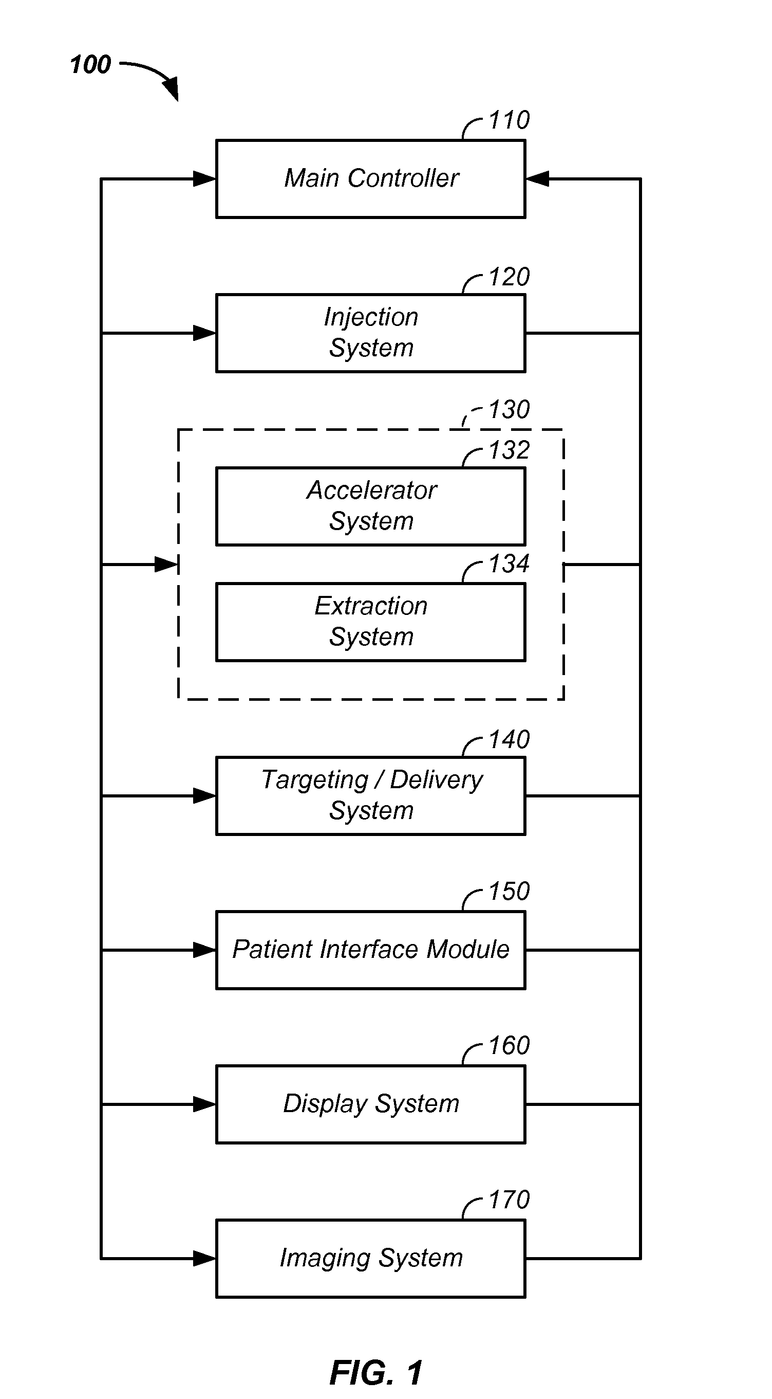
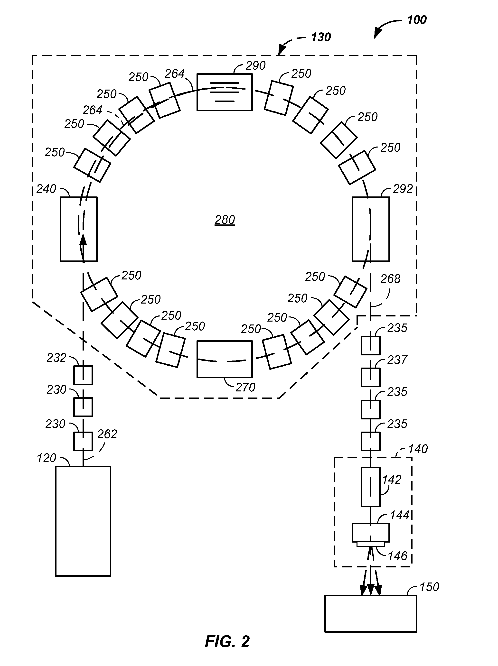
[0103]The invention comprises a charged particle beam extraction method and apparatus used in conjunction with charged particle beam radiation therapy of cancerous tumors.

[0104]The invention comprises a charged particle beam extraction method and apparatus used in conjunction with charged particle beam radiation therapy of cancerous tumors. The system uses a radio-frequency (RF) cavity system to induce betatron oscillation of a charged particle stream. Sufficient amplitude modulation of the charged particle stream causes the charged particle stream to hit a material, such as a foil element of a set of foils. The foil decreases the energy of the charged particle stream, which decreases a radius of curvature of the charged particle stream in the synchrotron sufficiently to allow a physical separation of the reduced energy charged particle stream from the original charged particle stream. Thickness of a selected foil is a function of energy of circulating charged particles. The physica...


PUM


Abstract

The invention comprises a charged particle beam extraction method and apparatus optionally used in conjunction with charged particle beam radiation therapy of cancerous tumors. The system uses a radio-frequency (RF) cavity system to induce oscillation of a charged particle stream. Sufficient amplitude modulation of the charged particle stream causes the charged particle stream to hit a material, such as a foil element of a set of foils. The foil decreases the energy of the charged particle stream, which decreases a radius of curvature of the charged particle stream in the synchrotron sufficiently to allow a physical separation of the reduced energy charged particle stream from the original charged particle stream where thickness of a selected foil is a function of energy of circulating charged particles. The physically separated charged particle stream is then removed from the system by use of an applied field and deflector.

Description

CROSS-REFERENCES TO RELATED APPLICATIONS[0001]This application:[0002]is a continuation-in-part of U.S. patent application Ser. No. 12 / 425,683 filed Apr. 17, 2009, now U.S. Pat. No. 7,939,809, which claims the benefit of:[0003]U.S. provisional patent application No. 61 / 055,395 filed May 22, 2008, now U.S. Pat. No. 7,939,809 B2;[0004]U.S. provisional patent application No. 61 / 137,574 filed Aug. 1, 2008;[0005]U.S. provisional patent application No. 61 / 192,245 filed Sep. 17, 2008;[0006]U.S. provisional patent application No. 61 / 055,409 filed May 22, 2008;[0007]U.S. provisional patent application No. 61 / 203,308 filed Dec. 22, 2008;[0008]U.S. provisional patent application No. 61 / 188,407 filed Aug. 11, 2008;[0009]U.S. provisional patent application No. 61 / 188,406 filed Aug. 11, 2008;[0010]U.S. provisional patent application No. 61 / 189,815 filed Aug. 25, 2008;[0011]U.S. provisional patent application No. 61 / 201,731 filed Dec. 15, 2008;[0012]U.S. provisional patent application No. 61 / 205,36...

Claims


Application Information

Patent Timeline
Patent Type & Authority Patents(United States)
IPC IPC(8): A61N5/00
CPCA61N5/10H05H7/10H05H13/04A61N2005/1087
Inventor BALAKIN, VLADIMIR
Owner BALAKIN ANDREY VLADIMIROVICH
Why Eureka
Try Eureka