Method and apparatus for reporting a missle threat to a commercial aircraft

a commercial aircraft and threat technology, applied in direction controllers, traffic control systems, instruments, etc., can solve problems such as low ground impact, false alarm rate must be very high, and the effect of affecting the flight is not easy to d

Inactive Publication Date: 2009-07-30
BAE SYST INFORMATION & ELECTRONICS SYST INTERGRATION INC
View PDF10 Cites 44 Cited by
  • Summary
  • Abstract
  • Description
  • Claims
  • Application Information

AI Technical Summary

Benefits of technology

[0033]Note also that all of the countermeasures, allocations, analyses, and evaluation of a countermeasure's effect is provided by a combination of the sensor subsystem and the Operational Flight Program running on the electronic control unit, ECU, embedded in the Operational Flight Program. The ECU is the electronic control unit that is part of the missile warning system.

Problems solved by technology

The challenge is to integrate this highly classified military missile warning system into a commercial aircraft which has to run at a completely unclassified level when transmitting the data to a ground station.
Thus, the problem is taking knowledge of the situation at the aircraft from a classified system and porting it to an unclassified system which then reports the information to the ground in an unclassified manner.
Therefore, the problem is going from a classified system to be able to generate a report that is useful on the ground in which the reporting system operates on an unclassified network.
The dilemma is that if one does not take precautions, then by simply connecting these two LANs together, one has brought the platform to the same level of security as the highly classified operational flight program for the aircraft.
However, the false alarm rate must be very, very low.
Depending on where the aircraft is at the time, the ground impact might be a problem for a missile that was diverted off course due to the countermeasuring.

Method used


Image

  • Method and apparatus for reporting a missle threat to a commercial aircraft
  • Method and apparatus for reporting a missle threat to a commercial aircraft
  • Method and apparatus for reporting a missle threat to a commercial aircraft

Examples


Embodiment Construction

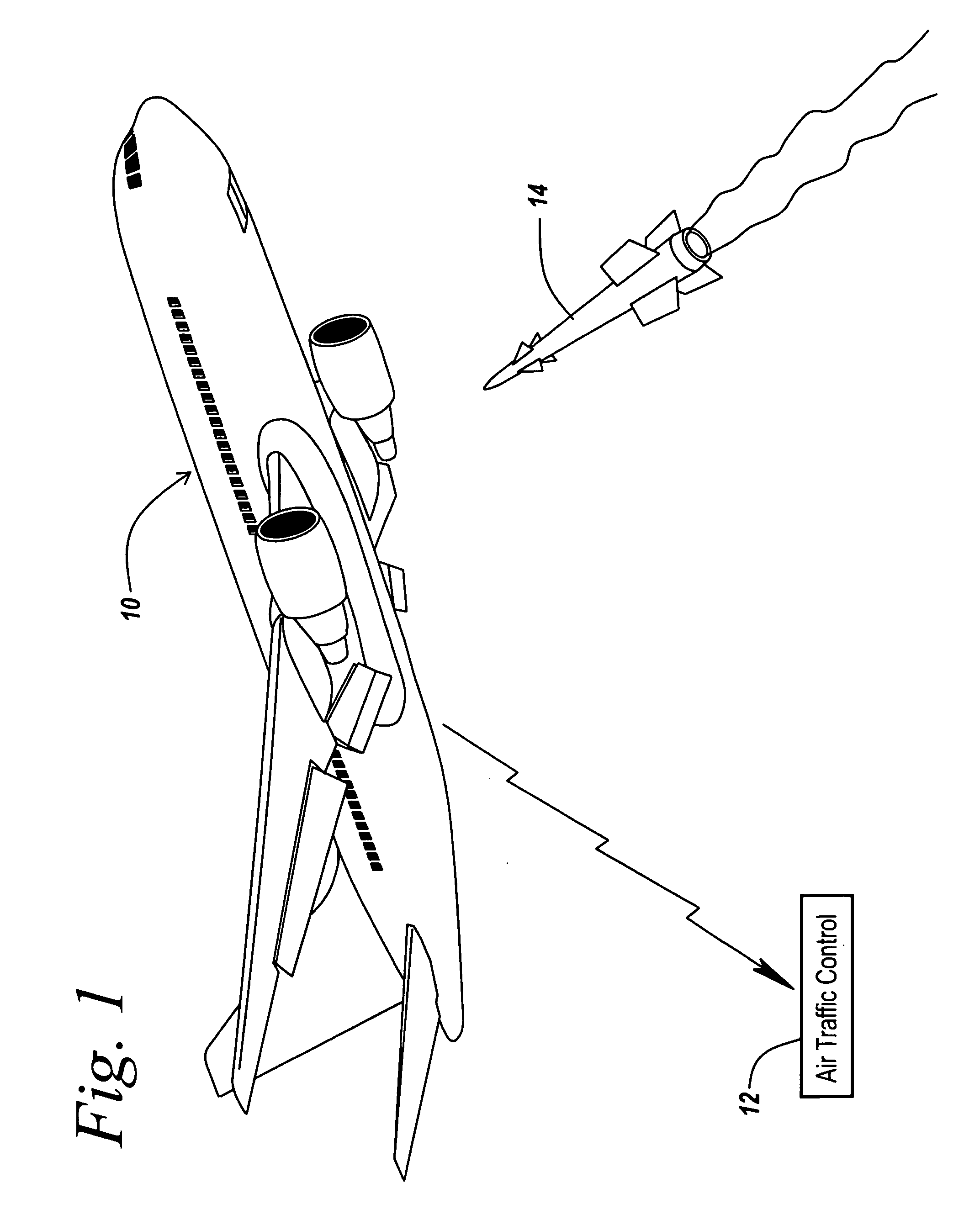
[0046]Referring now to FIG. 1, it is a requirement that commercial airliners, here illustrated at 10, be able to report to the ground, namely to air traffic control 12, that a missile 14 has been launched towards the aircraft. It is the purpose of the subject invention to detect the presence of the incoming signal, provide information about the incoming missile, and report the fact of the detection of a missile threat to the ground.

[0047]This is done to be able to alert ground personnel as to the situation regarding a missile attack on an aircraft and also to permit ground personnel to be able to take whatever corrective action is appropriate given the information transmitted from the aircraft.

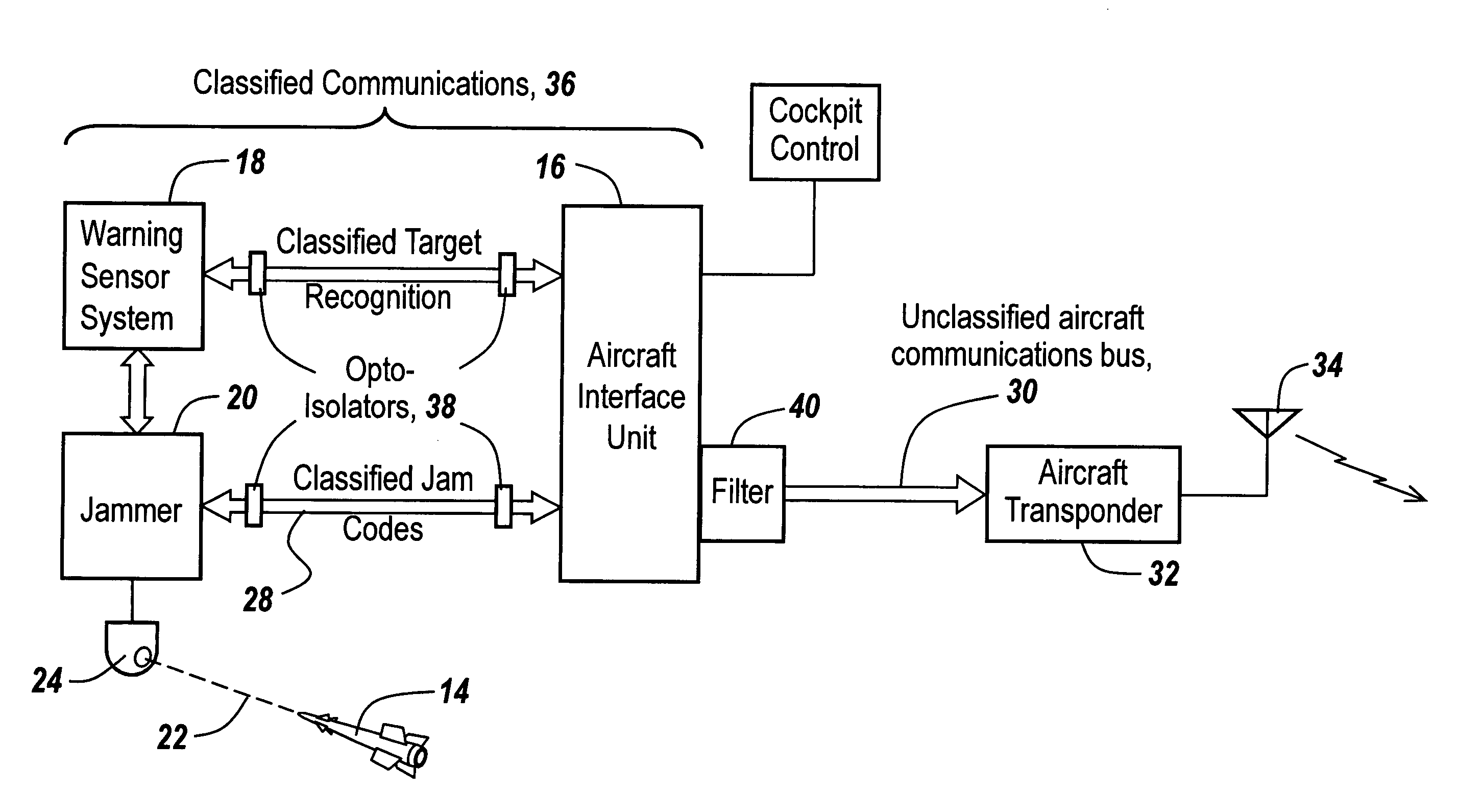
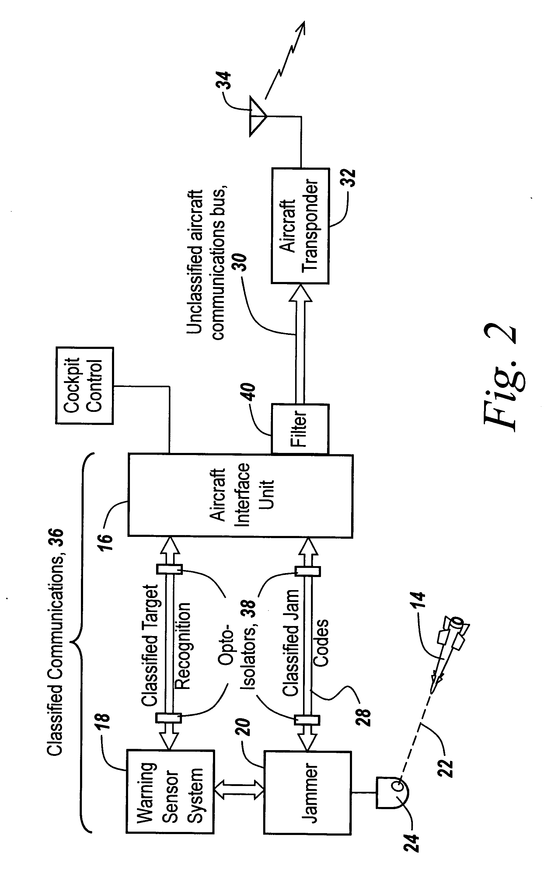
[0048]The aircraft transmits via its transponders the aircraft position information including position data or timing data and an indication in the form of an emergency notification (EN) that an event has occurred. The event's occurrence is in essence a declaration that a threat has been encou...


PUM


Abstract

An automatic system is provided for alerting ground personnel as to the existence of a threat to commercial aircraft in which the threat is determined by a classified system, but in which the local area network employed by the military missile warning is isolated from an unclassified local network coupled to the aircraft's transponder which transmits the threat existence and status to ground personnel. The barrier to transmitting classified information involves both filtering between the classified LAN and unclassified LAN, the use of only discrete signaling lines in the classified LAN isolated by opto-electronics to provide physical separation between the two local area networks, and communications formatting which precludes the transmission of classified information across the barrier between the classified local area network and the unclassified local area network.

Description

CROSS REFERENCE TO RELATED APPLICATION[0001]This application claims rights under 35 USC § 119(e) from U.S. Provisional Patent Application Ser. No. 61 / 062,237 filed Jan. 24, 2008, the contents of which are incorporated herein by reference.STATEMENT OF GOVERNMENT INTEREST[0002]This invention was made with United States Government assistance under Contract No. HSSCHQ-04-C-00342 awarded by the Department of Homeland Security. The United States Government has certain rights in this invention.FIELD OF THE INVENTION[0003]This invention relates to the reporting of a threat to a commercial airliner from heat seeking missiles and more particularly to the reporting of the threat to ground personnel without divulging classified information.BACKGROUND OF THE INVENTION[0004]As part of the Department of Homeland Security, there is a requirement for emergency notification to air traffic controllers if an attack on a commercial aircraft is detected. For this purpose, commercial airliners are provide...

Claims


Application Information

Patent Timeline
Patent Type & Authority Applications(United States)
IPC IPC(8): G08B21/00G01S7/38
CPCF41G7/224F41H11/02G08G5/0056H04K2203/24H04K3/825H04K2203/22H04K3/45H04L63/105H04L63/0227
Inventor KRAVITZ, ARNOLDSTOCKWELL, JASONZABLOCKI, EDWARDCLEMENCE, GEORGE
Owner BAE SYST INFORMATION & ELECTRONICS SYST INTERGRATION INC
Why Eureka
Try Eureka