
Assembly system for floor and/or wall tiles

a technology for floor and wall tiles and assembly systems, applied in the direction of sheet joining, flooring, fastening means, etc., can solve the problems of preventing the flexibility of assembling the covering elements in various directions, the patents of inventions described above also have this disadvantage, and it is not possible to optimize the assembly process. to achieve the effect of improving the general state of assembly

Active Publication Date: 2011-06-14
LLORENS VILAR
View PDF25 Cites 26 Cited by
  • Summary
  • Abstract
  • Description
  • Claims
  • Application Information

AI Technical Summary

Benefits of technology

[0002]Therefore, one object of the invention is the characteristic hidden means of assembly that facilitate the assembly process while ensuring the complete stability and immobilization of the tiles.
[0004]Another object of the invention is a particular tongue and groove system that optimizes maximally the tile joining process to create a specific wall or floor covering area. Therefore, this object of the invention is to achieve a perfectly flushed tile surface, as well as a correct guiding and placing mechanism of the tiles during the assembly process, ensuring a correct final positioning while expanding the combination possibilities, since the system object of the invention allows the tiles to be assembled on any one side of their perimeter.

Problems solved by technology

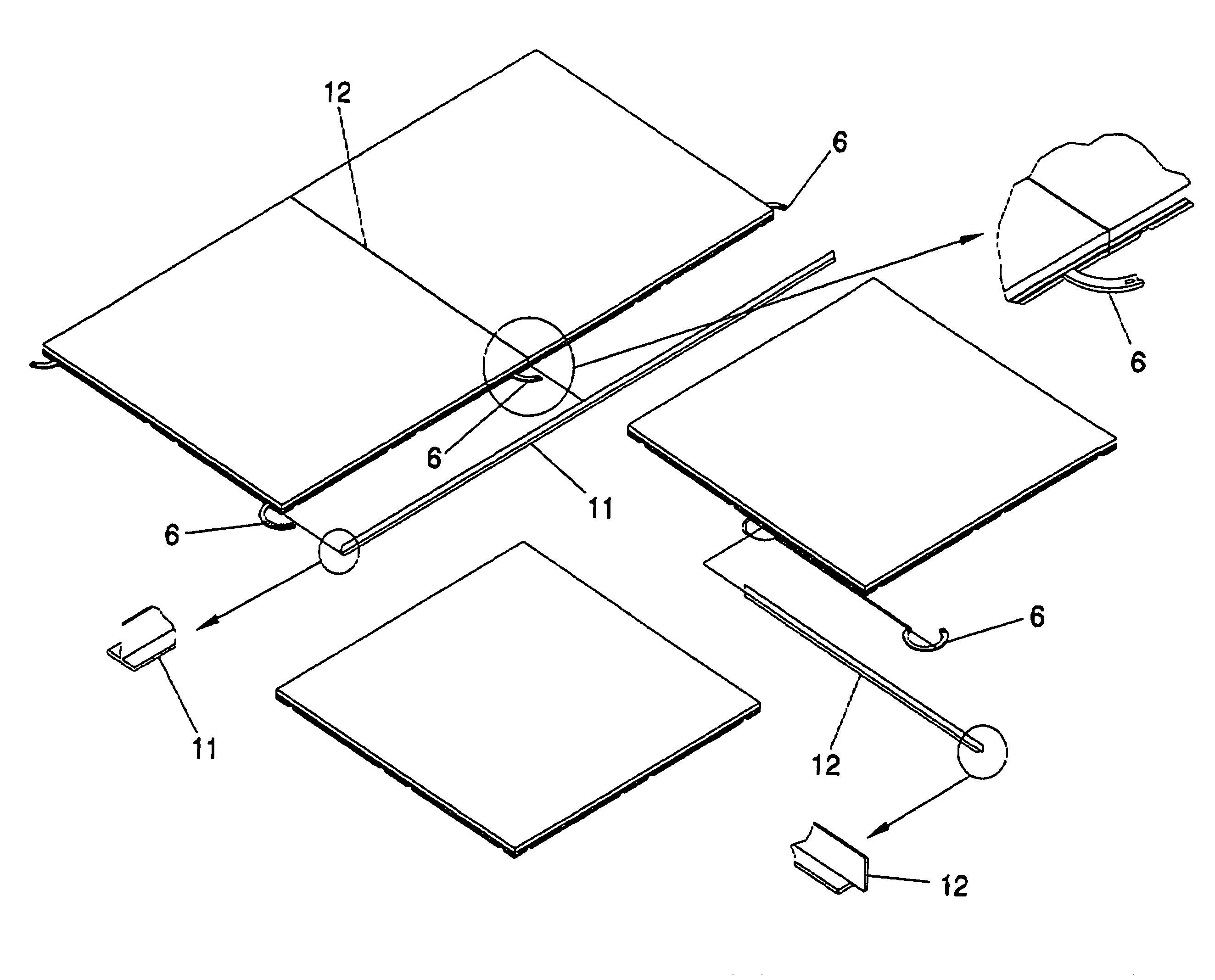
The current assembly systems are very diverse and are based on tiles that can be fitted together, although it has not been possible yet to optimize the assembly process due to various difficulties that have not yet been overcome and because the final results obtained may show mismatching or lack of flushing between the various individual tile elements.
These systems allow offset assembly systems in the longitudinal dimension, but without a clear reference point and permitting installation only in one direction, which precludes the flexibility of assembling the covering elements in various directions.
The inventions described in the Patents of Invention mentioned above also have this disadvantage.

Method used


Image

  • Assembly system for floor and/or wall tiles
  • Assembly system for floor and/or wall tiles
  • Assembly system for floor and/or wall tiles

Examples


Embodiment Construction

[0014]In order to attain the objectives of the invention and overcome the disadvantages of the systems mentioned in previous sections, the present invention proposes an assembly system for floor and / or wall tiles having significant improvements from conventional assembly systems, especially in terms of the ease and intuitiveness of installation, tile adjustment, and inclusion of assembly connecting elements or joints.

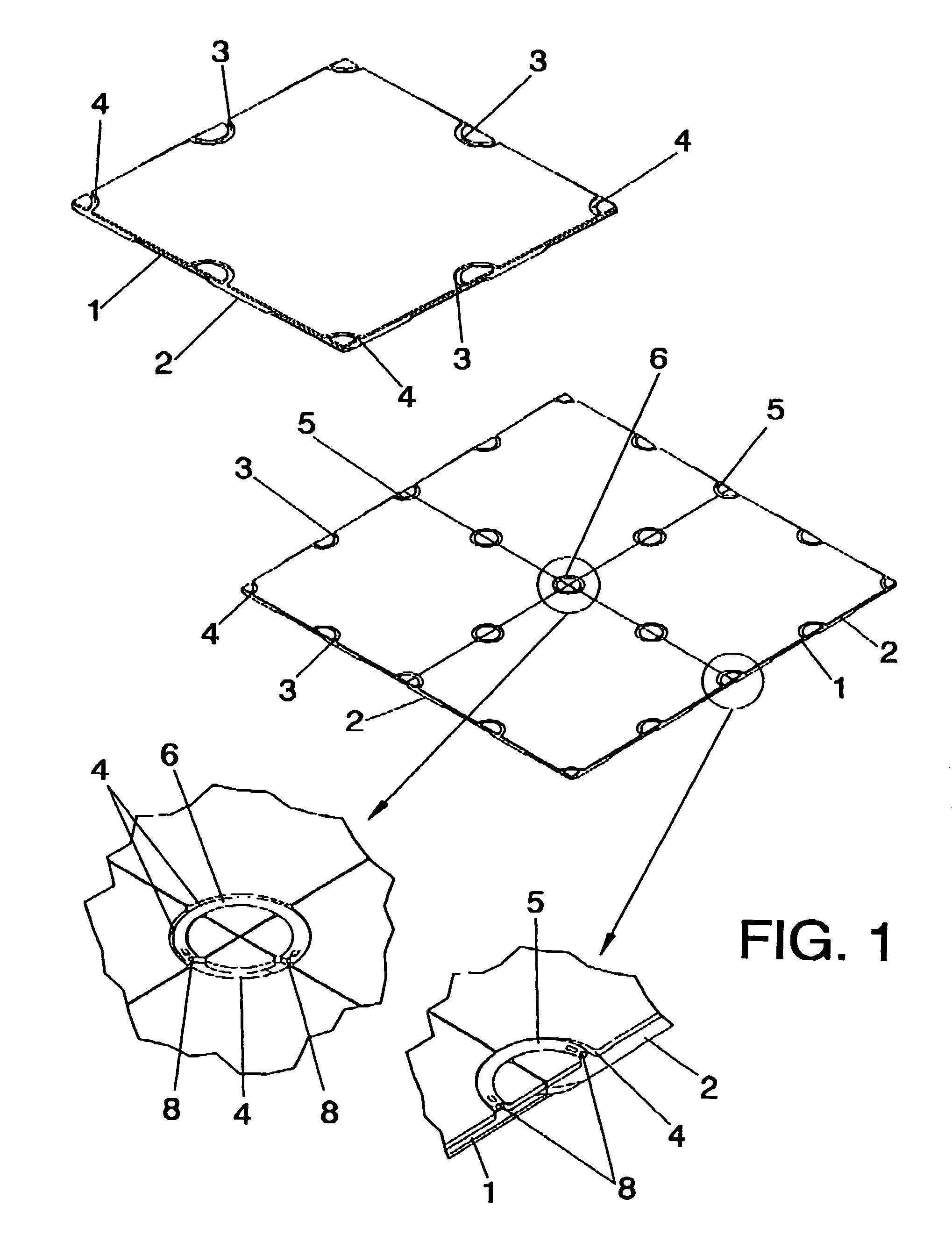
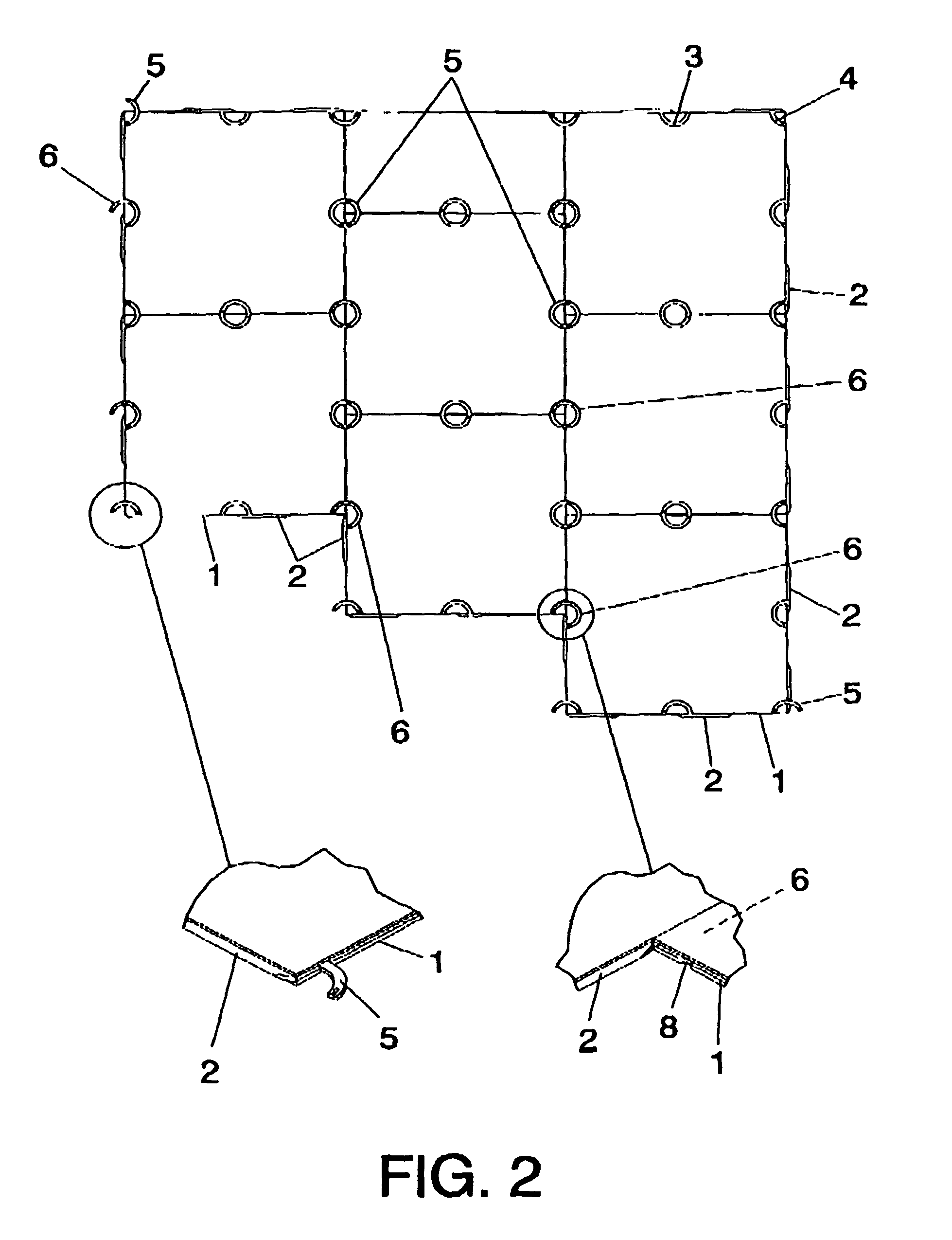
[0015]The system object of the invention is characterized in that it includes special anchoring means between tiles that are not visible once the floor has been installed, that is, said anchoring means are located in the tiles' underside.

[0016]These anchoring means are characterized in that they comprise male elements configured as curved structures that fit in a matching and complementary manner inside the corresponding annular channels or grooved elements located in the underside of the tiles.

[0017]These annular grooves having a closed contour affect, at leas, two adj...


PUM


Abstract

An assembly system for floor and / or wall tiles includes anchors between tiles arranged in a coplanar plane. The anchors are determined from portions curved in the shape of a groove located in the underside of the tiles and matching the side edges of the tiles that guide the curved portions to converge on the edges. When the tiles are put together next to each other head to head and at the point where the corners converge, these curved grooved portions form a channel on the underside of the tiles inside which male elements fit tightly in at least a portion of it to couple and engage at least two adjacent tiles.

Description

OBJECT OF THE INVENTION[0001]The present invention, as expressed in the title of this descriptive report, refers to an assembly system for floor and / or wall tiles applicable to assembly flooring such as a parquet type floor, made of wood or any other material, that are put together with assemblage means installed between the different parts or tiles that are the components of the flooring system.[0002]Therefore, one object of the invention is the characteristic hidden means of assembly that facilitate the assembly process while ensuring the complete stability and immobilization of the tiles.[0003]Another object of the invention is that it includes means to obtain a raised and removable modular floor that allows the extraction of some of the tiles in order to access the space below said tiles whenever necessary to inspect or repair the installations or utility networks running through the space created under the raised floor.[0004]Another object of the invention is a particular tongu...

Claims


Application Information

Patent Timeline
Patent Type & Authority Patents(United States)
IPC IPC(8): E04B2/00
CPCE04F13/0835E04F15/02E04F15/02005F16B5/006E04F2201/091E04F2201/095E04F2201/05E04F15/02022E04F15/02044E04F2015/02122
Inventor VILAR LLOP, NATIVIDADLLORENS MIRAVET, SALVADOR
Owner LLORENS VILAR
Learn More