Mobility assistance device

a technology of mobility assistance and support device, which is applied in the direction of walking aids, crutches, physical therapy, etc., can solve the problems of user's inability to provide adequate traction, undesirable reduction in stability of user, and user's tendency to fall to the side, so as to facilitate proper posture of user, facilitate the maximization of traction, and provide lateral stability

Inactive Publication Date: 2011-06-14
NO BOUNDARIES REHAB
View PDF9 Cites 4 Cited by
  • Summary
  • Abstract
  • Description
  • Claims
  • Application Information

AI Technical Summary

Benefits of technology

[0008]Compatible and attuned with the present invention, a mobility assistance device that facilitates a maximization of a traction between a feet of the device and a ground, and provides a lateral stability to a user, while facilitating a proper posture of the user, has surprisingly been discovered.

Problems solved by technology

A problem encountered by users when using conventional mobility assistance devices is that when the device is extended by the user at angles forwardly or rearwardly, the foot does not provide adequate traction due to minimal surface to surface contact with the ground.
Inadequate traction and minimal surface to surface contact between the foot and the ground surface can result in slippage and an undesirable reduction in a stability of the user.
Another problem associated with conventional mobility assistance devices is that the single foot provides minimal lateral stability assistance, which leaves the user susceptible to toppling to the sides.
Prior art solutions provide limited resolution to the traction and the lateral stability of the conventional mobility assistance devices that have a single foot.
However, the narrow elongate arcuate-shaped foot taught by the '704 patent does not provide stability in a lateral direction.
Additionally, the typical mobility assistance devices having a plurality of feet cause a handle thereof to be in a fixed and an awkward position in respect of the user.
The modified posture typically causes the user to modify his or her gait, which can reduce the stability and increase the fatigue of the user of the device.
Consequently, the user must either use the device improperly or modify his or her posture, both of which minimize the desired stability benefit of the mobility assistance device.

Method used


Image

  • Mobility assistance device
  • Mobility assistance device
  • Mobility assistance device

Examples


Embodiment Construction

[0022]The following detailed description and appended drawings describe and illustrate various exemplary embodiments of the invention. The description and drawings serve to enable one skilled in the art to make and use the invention, and are not intended to limit the scope of the invention in any manner.

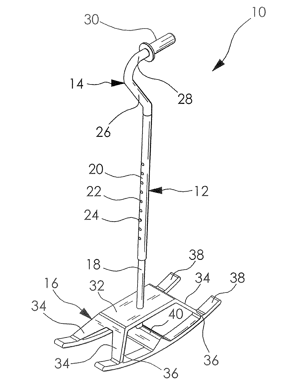
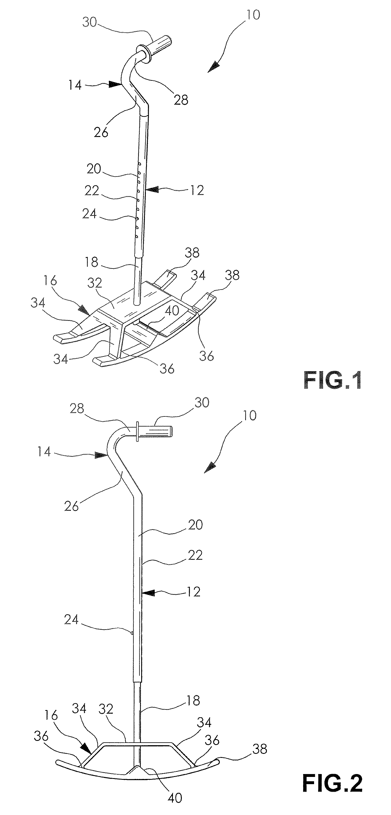
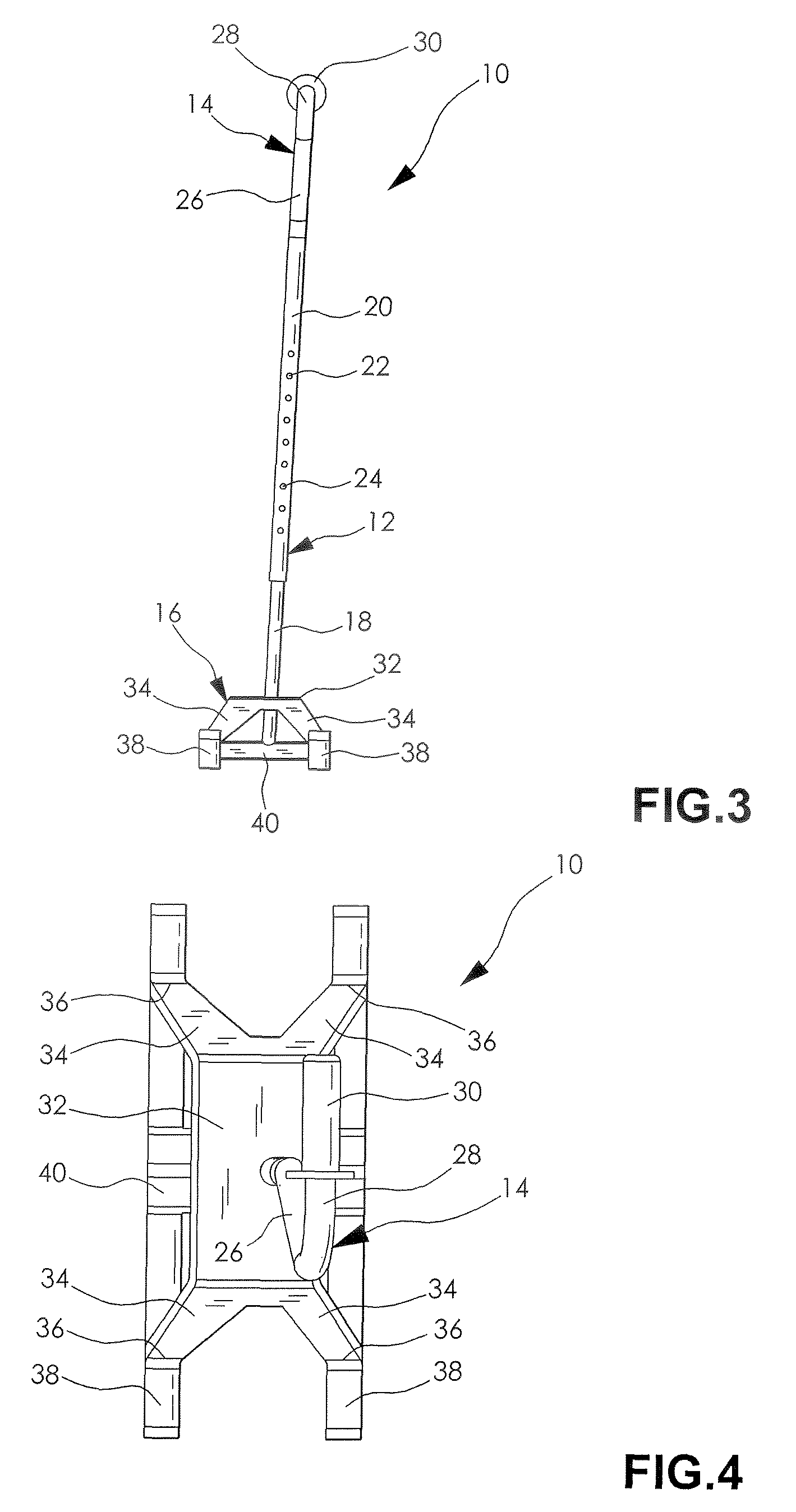
[0023]FIGS. 1-7 illustrate a mobility assistance device 10 in accordance with an embodiment of the invention. The mobility assistance device 10 includes a main shaft 12 having a handle 14 disposed at one end and a foot member or a ground engaging member 16 disposed at an opposite end thereof.

[0024]The main shaft 12 includes a pair of cooperating elongate members 18, 20 such as tubes for example. One end of member 18 is fixedly attached to the base member 18, and an opposite end thereof is adjustably connected to one end of the elongate member 20. It should be understood that the one end of elongate member 18 can be removably attached to foot member 16. In the embodiment shown, the el...


PUM


Abstract

A mobility assistance device is disclosed including a main shaft having a handle attached to one end thereof and a ground engaging member attached to an opposite end. The ground engaging member includes a support member and at least one generally arcuate-shaped foot depending therefrom adapted to contact a supporting surface that facilitates a maximization of a traction and a surface to surface contact between the arcuate-shaped foot and the supporting surface. The shaft and the handle are oriented in respect of the ground engaging member to facilitate a proper posture and a gait of a user, thereby maximizing a stability of the user.

Description

FIELD OF THE INVENTION[0001]The present invention relates to a mobility assistance device, and more particularly to a mobility assistance device having an arcuate-shaped foot portion and a handle portion attached thereto adapted to maximize a stability of a user.BACKGROUND OF THE INVENTION[0002]Mobility or walking assistance devices such as canes and crutches, for example, have frequently been employed to offer stability to those who require mobility assistance. Conventional walking assistance devices comprise a main body portion which is typically a bar or pole formed from wood or metal. The devices are typically cut to a desired length. The devices also include a handle portion disposed at an upper part of the main body, and a foot portion disposed at a lower part of the main body. Typically, the foot portion includes a rubber cap having a flat surface for contacting the ground.[0003]The conventional mobility assistance devices typically have a single foot. A problem encountered b...

Claims


Application Information

Patent Timeline
Patent Type & Authority Patents(United States)
IPC IPC(8): A45B9/04
CPCA45B9/04
Inventor RUDDY, KEVIN C.
Owner NO BOUNDARIES REHAB
Why Eureka
Try Eureka