
Versatile pole support, system and method

a technology of pole support and telescopic pole, applied in the direction of machine supports, washstands, collapsible antennas, etc., can solve the problems of reducing the safety of users and equipment, and reducing the usefulness of conventional telescopic pole systems, so as to prevent high torque loads and reduce the usefulness of the system, the effect of maximum safe extension

Inactive Publication Date: 2011-06-14
DORN MARK
View PDF18 Cites 0 Cited by
  • Summary
  • Abstract
  • Description
  • Claims
  • Application Information

AI Technical Summary

Benefits of technology

[0003]Poles are used to elevate devices or support a variety of equipment, ranging from communication applications to lighting. Portability of such poles has traditionally constrained wider applications for poles. One improvement in this area is the development of telescopic poles. However, for most telescopic pole consumers, raising a pole to elevation is a time consuming endeavor requiring thoughtful selection of terrain and careful attention to pole angle to obtain a near vertical pole orientation, thus allowing the user a maximum safe extension. For example, if a pole is improperly extended and is not vertical, a fulcrum effect exists which creates torque about its base. This torque presents a danger to the user and equipment due to possible mechanical failure of the pole or pole support. Many poles are height limited or use cumbersome guy wires to prevent high torque loads, thus reducing their usefulness.
[0005]There is thus a need for a device, system and / or method that provides a lightweight, compact, adjustable, fast erecting, vehicle mountable or self-supporting and easily transportable pole stabilizing method and apparatus that is capable of operating on uneven terrain.
[0006]The present invention provides, in part, a pole support and method that can adjust to a vertical position irrespective of the slope or grade of the terrain. The present invention further provides, in part, a dual pivoting pole support having members that can pivot about non-parallel axes so as to provide true, multi-dimensional leveling. The present invention further provides, in part, a pole mounting system for assisting in remote surveillance whereby a pole mounted camera or other device and multiple support parts can be directed by remote computer so as to adapt for local conditions without requiring personnel on-site. In addition, the pole support system may articulate to position the pole vertically, either automatically by leveling gyroscope or computer, or manually, whereby the operator uses an input device to send signals; which through actuators, manipulate the pole to a vertical orientation on sloping terrain.

Problems solved by technology

However, for most telescopic pole consumers, raising a pole to elevation is a time consuming endeavor requiring thoughtful selection of terrain and careful attention to pole angle to obtain a near vertical pole orientation, thus allowing the user a maximum safe extension.
This torque presents a danger to the user and equipment due to possible mechanical failure of the pole or pole support.
Many poles are height limited or use cumbersome guy wires to prevent high torque loads, thus reducing their usefulness.
Conventional telescopic pole systems suffer from a number of drawbacks.
This approach cannot adapt to a sloping, terrain.
That is, the rigidness cannot be adjusted to a vertical orientation.
In addition, a trailer mounted pole stabilizer, in general, is large and heavy, and thus, less easily transported and positioned.
Further, a larger storage area is required for such a stabilizer.
This approach is impractical on sloping terrains because the pole assumes an angle perpendicular to the terrain.

Method used


Image

  • Versatile pole support, system and method
  • Versatile pole support, system and method
  • Versatile pole support, system and method

Examples


Embodiment Construction

[0020]An apparatus, method, and system for supporting a pole are disclosed. In the following description, for the purposes of explanation, numerous specific details are set forth in order to provide a thorough understanding of the embodiments of the invention. It is apparent, however, to one skilled in the art that the embodiments of the invention may be practiced without these specific details or with an equivalent arrangement. In other instances, well-known structures and devices are shown in block diagram form in order to avoid unnecessarily obscuring the embodiments of the invention.

[0021]Although the embodiments of the invention are discussed with respect to a telescopic pole, it is recognized by one of ordinary skill in the art that the embodiments of the inventions have applicability to any type of physical structure that may be substituted for the pole (e.g., an antenna).

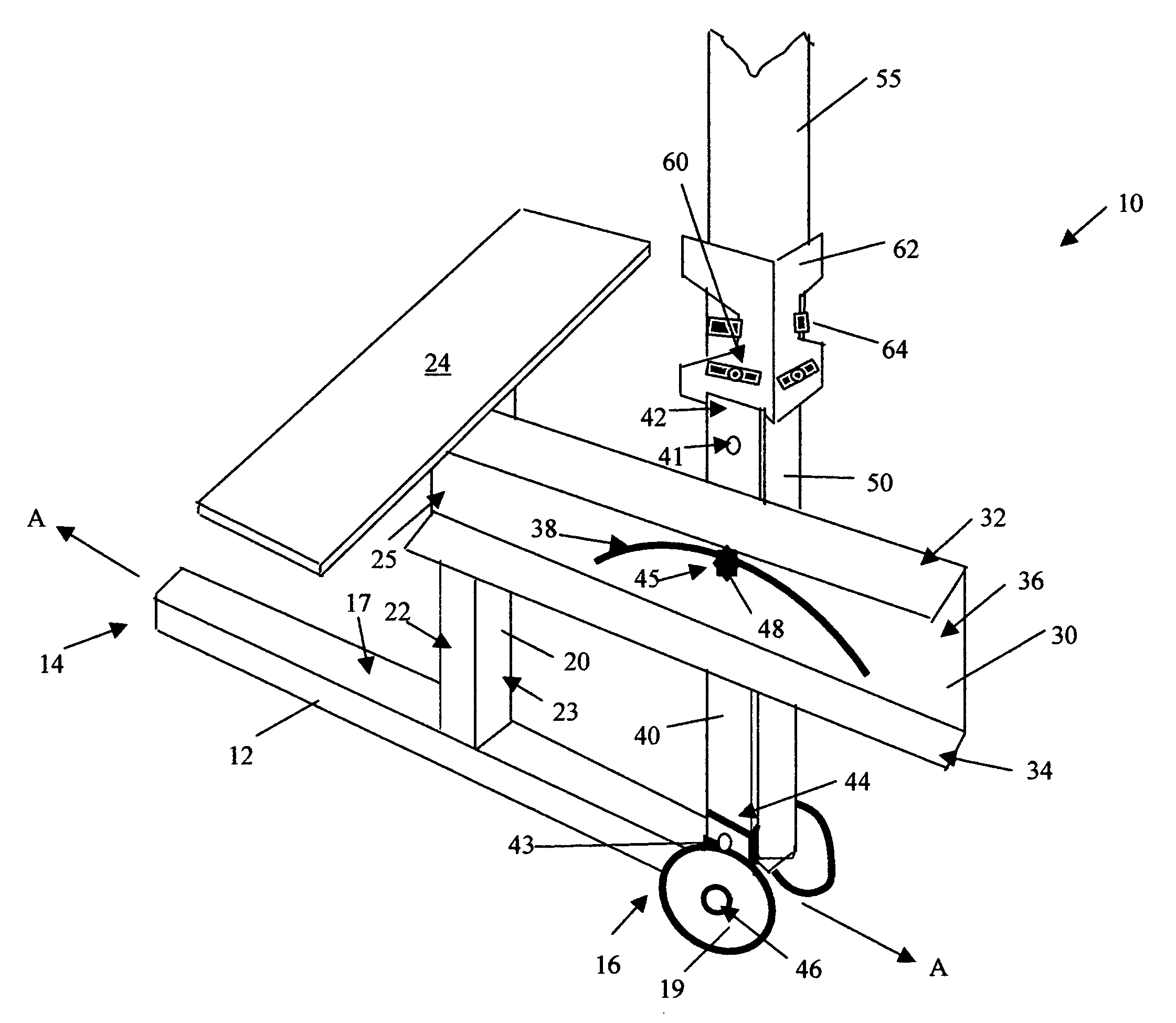
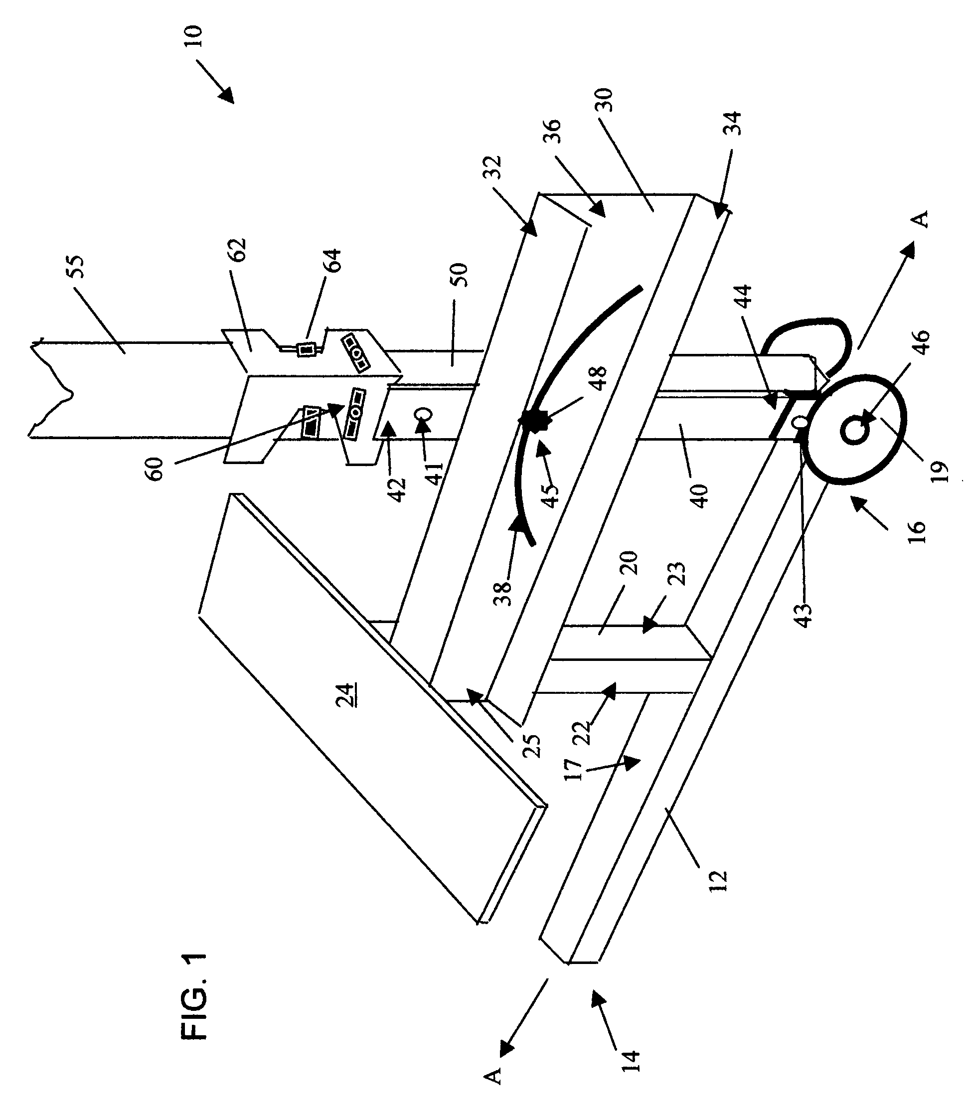
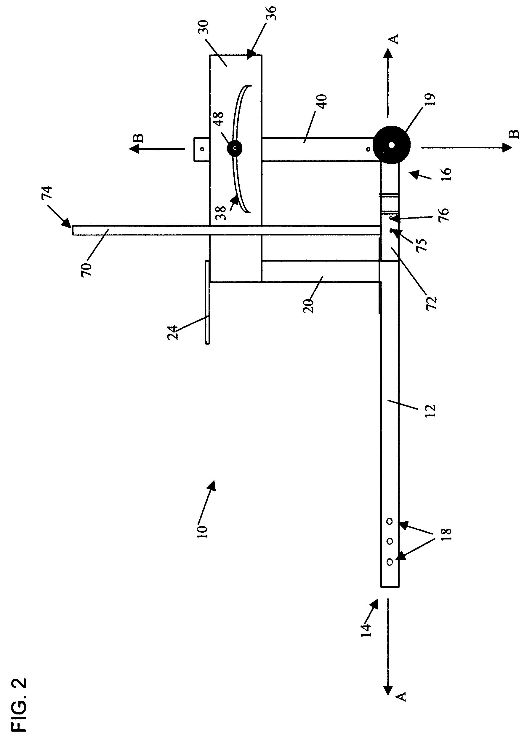
[0022]As shown in FIGS. 1, 2, 6, 7 and 11, one embodiment of the pole support 10 of the present invention...


PUM

PropertyMeasurementUnit
heightaaaaaaaaaa
lengthaaaaaaaaaa
diameteraaaaaaaaaa

Abstract

An apparatus includes a lockable, adjustable pole support rail allowing a user to adjust a mounted pole to vertical on sloping terrain. The apparatus has multiple embodiments and useful applications, in that it can be attached to a vehicle's hitch receiver, or can be self-supporting utilizing fold-out stabilizing or attachable legs, for example. In addition, the apparatus may include wheels, thus permitting ease of transport to or from a vehicle. The pole can be deployed with a range of attachments or devices depending on the application. Exemplary applications include a photography camera, a surveillance camera, an infra-red camera, an antenna, loudspeakers, lighting equipment, signage, weather monitoring equipment, inspection equipment, and detection equipment.

Description

CROSS-REFERENCE TO RELATED APPLICATIONS[0001]The present application claims the benefit of U.S. Application Ser. No. 60 / 842,813 filed Sep. 7, 2006 and entitled “Pole Support System,” the specification of which is incorporated herein in its entirety.FIELD OF THE INVENTION[0002]The present invention relates to a pole support system, and more particularly to a portable pole support system that can adapt to uneven terrain to provide a level support for a variety of items.BACKGROUND AND SUMMARY OF THE INVENTION EMBODIMENTS[0003]Poles are used to elevate devices or support a variety of equipment, ranging from communication applications to lighting. Portability of such poles has traditionally constrained wider applications for poles. One improvement in this area is the development of telescopic poles. However, for most telescopic pole consumers, raising a pole to elevation is a time consuming endeavor requiring thoughtful selection of terrain and careful attention to pole angle to obtain a...

Claims


Application Information

Patent Timeline
Patent Type & Authority Patents(United States)
IPC IPC(8): F16M11/00
CPCH01Q1/10H01Q1/1235H01Q1/1242H01Q1/3216H01Q1/125Y10T29/49826Y10S224/924
Inventor MADSEN, PAUL C.
Owner DORN MARK
Learn More