
Photon event distribution sampling apparatus and method

a distribution sampling and photon event technology, applied can solve the problems of pixel-based scanning typically allowing for reduced flexibility in experiment design, physical and mechanical constraints, and the quality of output signal to be produced in the field of high sensitivity imaging apparatus

Inactive Publication Date: 2011-06-14
BOARD OF RGT NEVADA SYST OF HIGHER EDUCATION ON BEHALF OF THE UNIV OF NEVADA RENO
View PDF9 Cites 4 Cited by
  • Summary
  • Abstract
  • Description
  • Claims
  • Application Information

AI Technical Summary

Benefits of technology

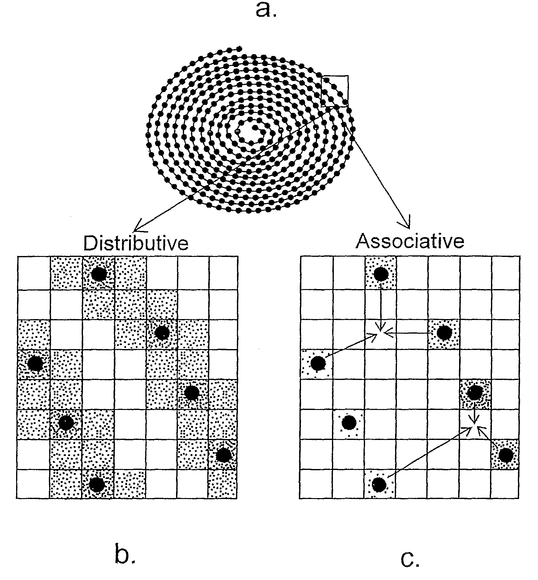
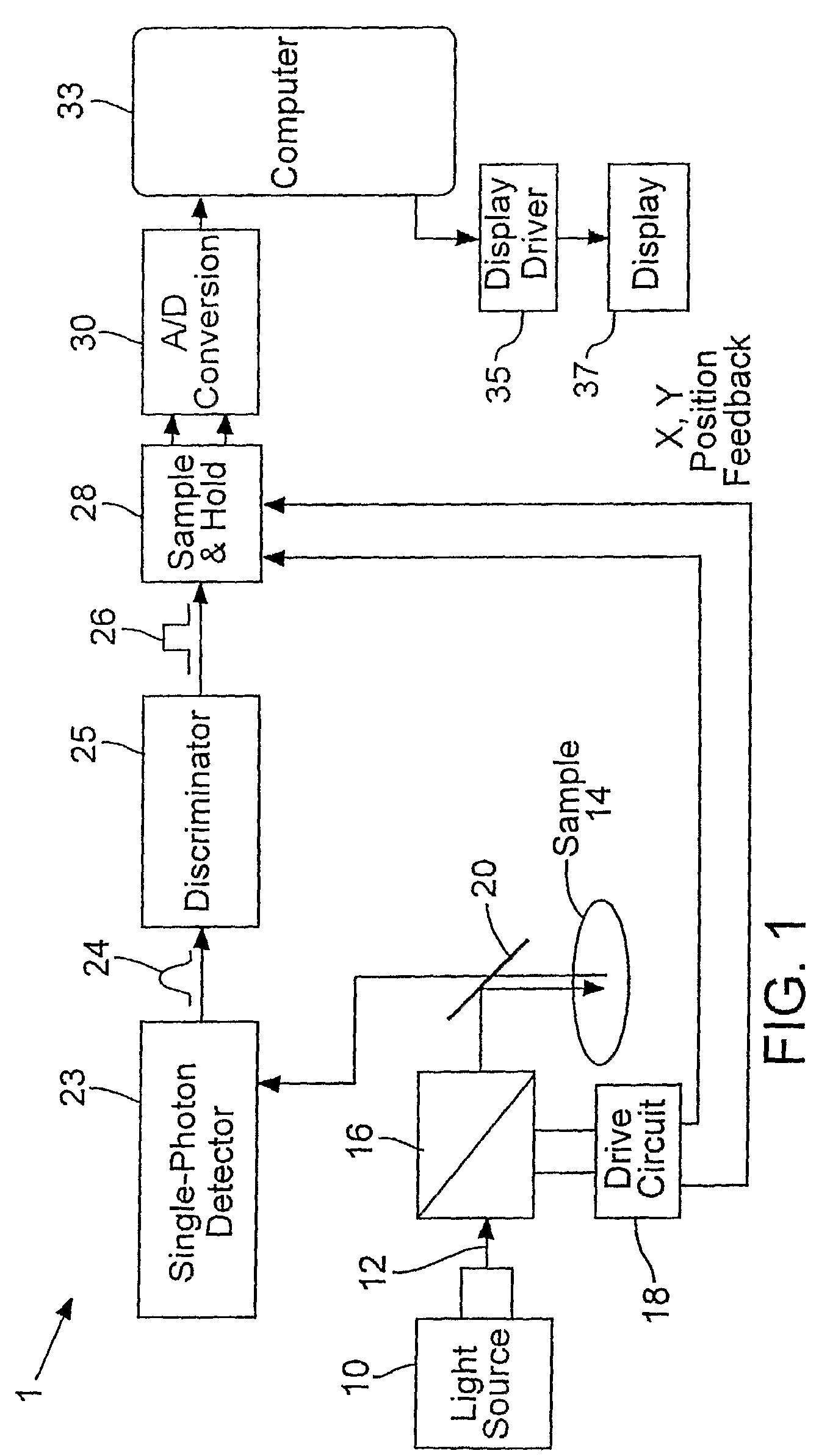
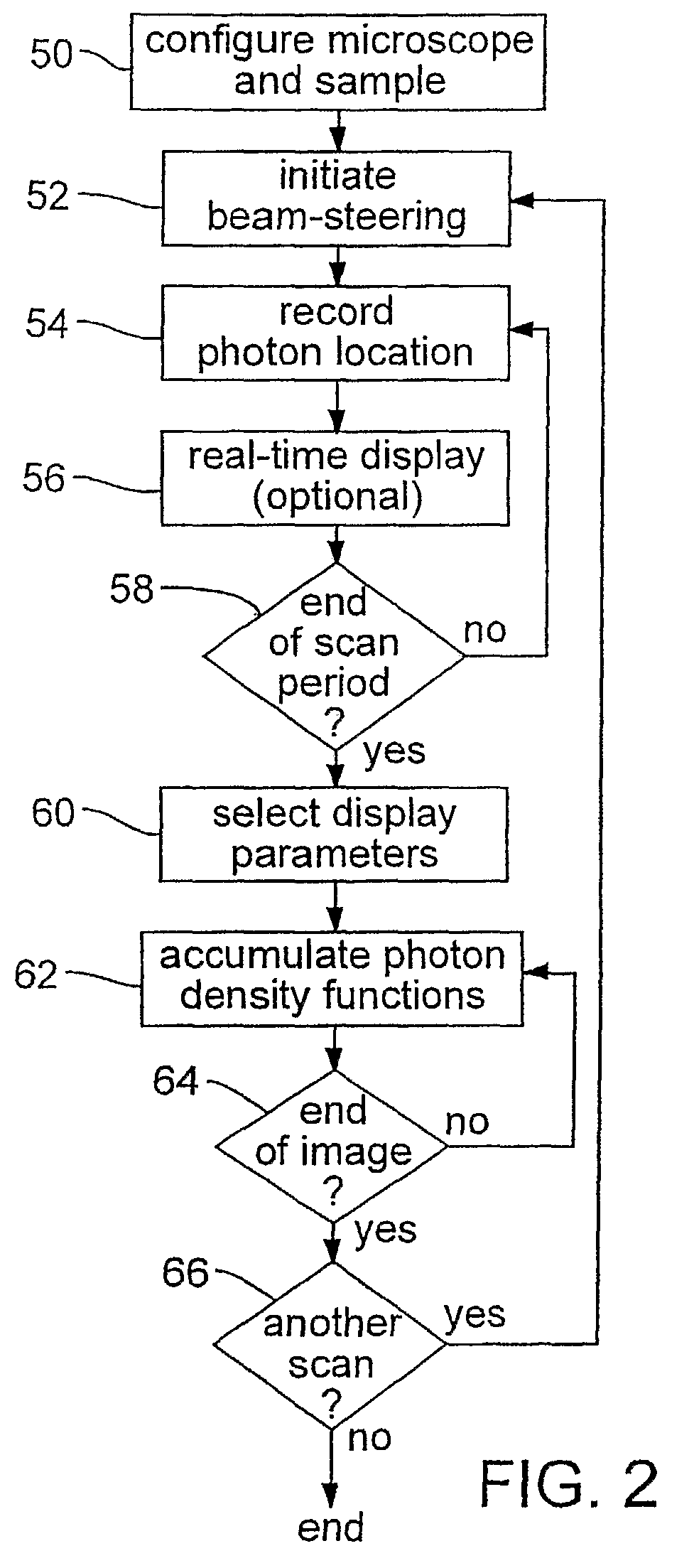
[0020]Certain embodiments measure each photon position by a position function associated with the position. One exemplary position function is photon probability density. The technique then sums or otherwise processes the photon probability density functions, which can require fewer photons to converge to an ideal density distribution associated with an image feature than are required using conventional pixel binning. Consequently, the same number of photons may be counted to yield increased spatial resolution. Sensitivity of measurement can be improved. Since fewer photons need be detected for a given resolution, less excitation illumination of a sample to produce photons is required than with conventional pixel binning. The technique thus can eliminate or reduce over-illumination of samples and its concomitant adverse effects.
[0025]For further precision, in certain embodiments the effect of various possibly interfering phenomena may be reduced or eliminated. These phenomena can include sampling delays that may occur in the acquisition of x-y position information and photon detection, differences between the positions indicated by the signal indicative of scanner positions and actual scanner positions. Other such phenomena may be the result of inertia of a scanning element or torque in an arm that rotates to drive a scanning component. Torque can result in different angular positions of opposite ends of a drive arm. By taking these types of phenomena into account, precision may be even further improved in certain embodiments of the present invention.
[0027]Availability of complete sets of data in time and space can enable further forms of processing of the data, including post-hoc analysis. Post-hoc analysis of the data can allow further analysis of the sample even after the sample may become either unavailable or unresponsive to further excitation radiation.

Problems solved by technology

As a result, prior art pixel-based imaging systems face constraints in scan rate with regard to the quality of output signal to be produced.
Physical and mechanical constraints, such as the rate at which a scanner can move, are also present.
As a result, pixel based scanning typically allows for reduced flexibility in experiment design.
The requirement for greater illumination has functional drawbacks.
Over illumination also presents another drawback.
Where measurements are made in vivo, emission of a photon from tissue causes free radicals, which can damage cells.
Therefore, over-illumination of tissue can result in photo-toxicity.
A limitation of typical prior art techniques is that they are optically based.
The resolving power of a lens is ultimately limited by diffraction effects.
Light passing through it interferes with itself, creating a ring-shaped diffraction pattern known as the Airy pattern, that blurs the image.
Optical techniques do not afford the opportunity to obtain resolution beyond the diffraction limit.
The Applicants have discovered that prior art pixel-based imaging techniques lose information.
For example, information typically is lost due to binning of photons.
This summing results in the loss of spatial and temporal information for individual photons.
Quality of a displayed image is limited only by the quality of display apparatus and not by the quality of the data.

Method used


Image

  • Photon event distribution sampling apparatus and method
  • Photon event distribution sampling apparatus and method
  • Photon event distribution sampling apparatus and method

Examples


example

Application

[0062]One application of an embodiment of the present invention is measurement of release of calcium ion, Ca2+, from intracellular sarcoplasmic reticulum (SR) stores in cardiac cells. Ca2+ release activates the contractions of the heart in order to pump blood throughout the body. Ca2+ is released through ryanodine receptor (RyR) Ca2+ channels present in SR membranes and information concerning the functional properties of these channels, as they exist inside of heart cells, can help in understanding how contraction of the heart is activated and regulated. Since RyR channels are present in intracellular membranes, they cannot be studied using conventional microelectrode-based electrophysiological techniques. However, changes in intracellular Ca2+ can be measured non-invasively by monitoring fluorescence from dyes, such as fluo-3 introduced into the cytoplasm of the cell, which increases when Ca2+ binds to the dye.

[0063]Small increases in fluo-3 fluorescence observed in card...


PUM

PropertyMeasurementUnit
mean diameteraaaaaaaaaa
diameteraaaaaaaaaa
diameteraaaaaaaaaa

Abstract

Locations of the origins of the photons are acquired from a scanned sample with reference to a scan frame. The location on the sample from which a photon was emitted is inferred from the location of the scan as commanded by a scan drive signal, a feedback signal related to the position of the scan device, or alternatively by the point in time during a scan at which the photon is detected. A position function, e.g., photon probability density, is associated with a photon position. Summing or other processing of photon probability density functions can require fewer photons to converge to an ideal density distribution associated with an image feature than are required using conventional pixel binning. Stored data can be mapped into pixels or voxels of a display or otherwise processed. Original data remains available in the digital storage for post-hoc analysis. Imprecision introduced by the display process need not adversely affect the precision of the collected data.

Description

CROSS REFERENCE TO RELATED APPLICATIONS[0001]This is the U.S. National Stage of International Application No. PCT / US2005 / 017948, filed May 20, 2005, which was published in English under PCT Article 21(2), which in turn claims the benefit of U.S. Provisional Application No. 60 / 573,459, filed May 20, 2004. Both applications are incorporated herein in their entirety.STATEMENT OF GOVERNMENT SUPPORT[0002]The invention was made by an agency of the United States Government or under a contract with an agency of the United States Government. The name of the U.S. Government agency and the Government contract number are: National Science Foundation, Grant / Contract No. EPS0132556. The U.S. Government has certain rights in the invention.FIELD OF INVENTION[0003]This invention concerns high sensitivity imaging apparatus, especially optical systems for examining reflected, fluorescent or chemiluminescent radiation.BACKGROUND OF THE INVENTION[0004]Detecting photons and producing electronic images fr...

Claims


Application Information

Patent Timeline
Patent Type & Authority Patents(United States)
IPC IPC(8): G01J1/00G01B11/00G01N21/64G02B21/16H04N7/18
CPCG01N21/6456G02B21/16G01N21/6458
Inventor SUTKO, JOHN L.PUBLICOVER, NELSON G.
Owner BOARD OF RGT NEVADA SYST OF HIGHER EDUCATION ON BEHALF OF THE UNIV OF NEVADA RENO
Learn More