
Viewfinder optical system, optical apparatus using the same and method for expanding observation

a technology of optical system and viewfinder, which is applied in the field of viewfinder optical system and optical apparatus using can solve the problems of reducing the observation magnification of the viewfinder optical system, and reducing the observation magnification. effect of observation

Inactive Publication Date: 2011-06-14
NIKON CORP
View PDF15 Cites 6 Cited by
  • Summary
  • Abstract
  • Description
  • Claims
  • Application Information

AI Technical Summary

Benefits of technology

[0016]According to the present invention, it becomes possible to provide a viewfinder optical system capable of obtaining a given observation magnification and a given distance between the eyepiece and the eyepoint, and suitable for an SLR digital camera and an SLR camera, and to provide an optical apparatus using the viewfinder, and a method for expanding observation.

Problems solved by technology

However, in this way, since the eyepiece optical system falls back from the rear side of the camera to the front side thereof, it becomes difficult to put an observer's eye near to the eyepiece optical system.
On the other hand, when the distance between the eyepiece and the eyepoint is made sufficiently long, an effective diameter at the exit surface of the erecting image forming member has to be large resulting in inevitably lengthening the optical path length of the erecting image forming member, so that observation magnification of the viewfinder optical system becomes small.
In the case of an SLR digital camera, since a display member for confirming an image is disposed on the rear side thereof, it becomes further difficult to observe the viewfinder of the camera unless the eyepiece optical system is disposed closer to the rear side of the camera than before.
Moreover, when the observer wears glasses, unless the diopter scale is fitted to the observer, the observer's eye has to be closer to the eyepiece optical system, so that the observer finds it difficult to observe the viewfinder of the camera.
However, the disclosed example of Japanese Patent Application Laid-Open No. 2003-215471 cannot secure sufficient observation magnification.
Accordingly, when a small-size solid-state imaging device, which is used in an SLR digital camera, is used, the image capable of being observed by the viewfinder optical system becomes extremely small.
When all the requirements are made to be satisfied, the whole optical system becomes complicated, so that it becomes difficult to satisfactorily show respective functions' ability.

Method used


Image

  • Viewfinder optical system, optical apparatus using the same and method for expanding observation
  • Viewfinder optical system, optical apparatus using the same and method for expanding observation
  • Viewfinder optical system, optical apparatus using the same and method for expanding observation

Examples


example 1

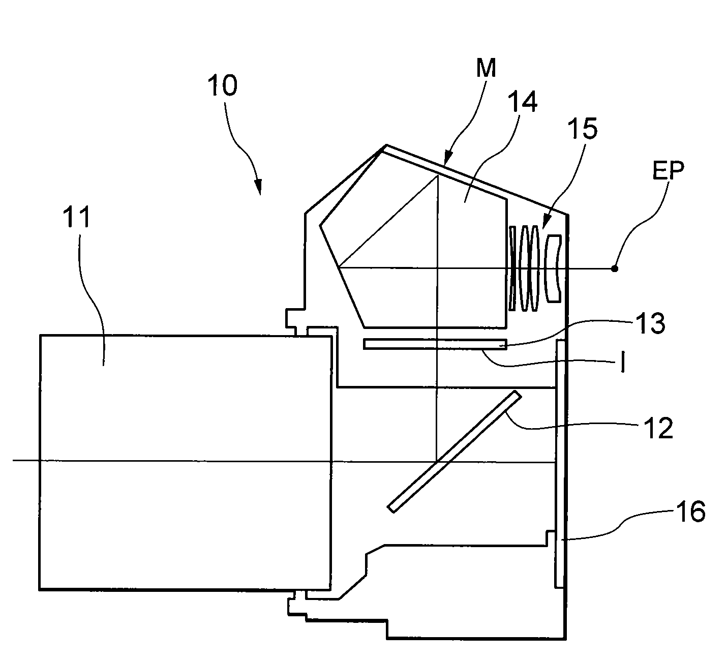
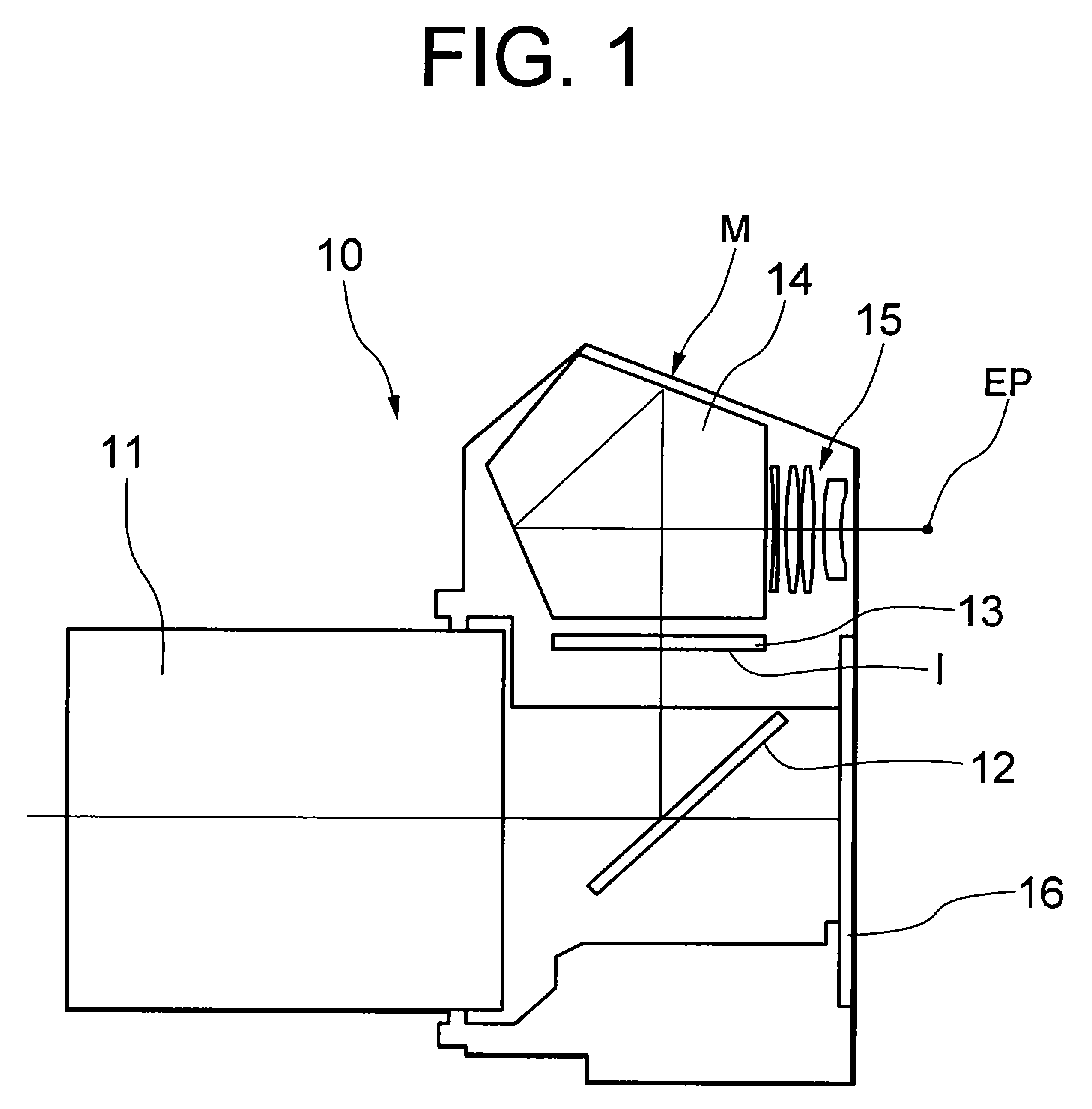
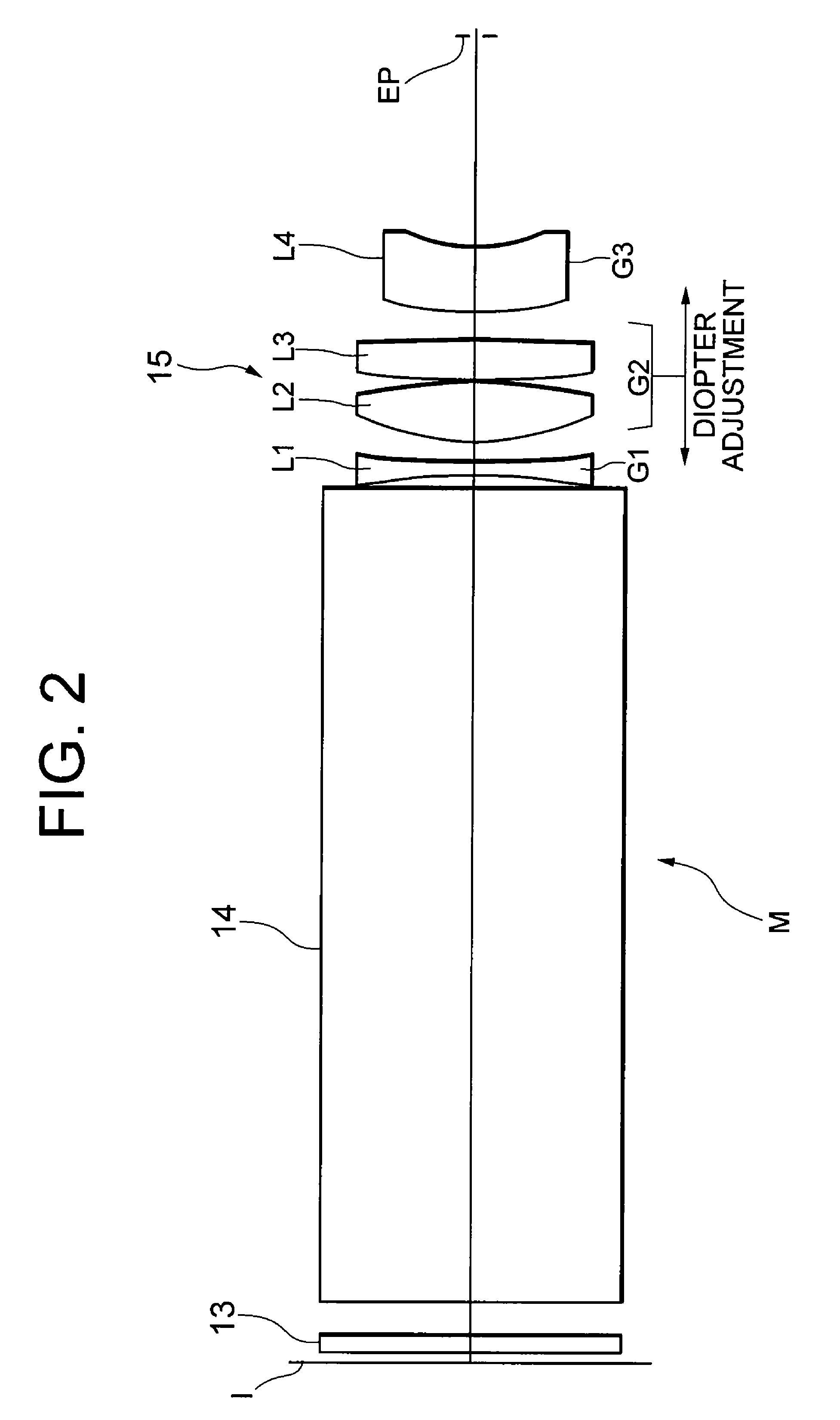
[0048]FIG. 2 is a diagram showing a construction of optical elements of a viewfinder optical system M according to Example 1 of the present embodiment, in which the diopter scale of an eyepiece optical system 15 is −1.0 diopter. As shown in FIG. 1, the optical path of the viewfinder optical system M is folded, however, the optical path is extended in the diagram.

[0049]In the viewfinder optical system shown in FIG. 2, a real image of an object formed on a focusing screen 13 disposed in the vicinity of an image plane I of an objective lens 11 shown in FIG. 1 is incident on an eyepiece optical system 15 through an erecting image forming member 14.

[0050]The eyepiece optical system 15 is composed of, in order from the focusing screen 13 side along an optical axis, a first lens group G1 constructed by a double concave negative lens L1, a second lens group G2 constructed by a double convex positive lens L2 and a double convex positive lens L3, and a third lens group G3 constructed by a neg...

example 2

[0058]FIG. 4 is a diagram showing a construction of optical elements of a viewfinder optical system M according to Example 2 of the present embodiment, in which the diopter scale of an eyepiece optical system 15 is −1.0 diopter.

[0059]In the viewfinder optical system shown in FIG. 4, a real image of an object formed on a focusing screen 13 disposed in the vicinity of an image plane I of an objective lens 11 shown in FIG. 1 is incident on an eyepiece optical system 15 through an erecting image forming member 14.

[0060]The eyepiece optical system 15 is composed of, in order from the focusing screen 13 side along an optical axis, a first lens group G1 constructed by a double concave negative lens L1, a second lens group G2 constructed by a double convex positive lens L2 and a double convex positive lens L3, and a third lens group G3 constructed by a negative meniscus lens L4 having a concave surface facing an eyepoint EP side. Light passing through the eyepiece optical system 15 reaches ...

example 3

[0065]FIG. 6 is a diagram showing a construction of optical elements of a viewfinder optical system M according to Example 3 of the present embodiment, in which the diopter scale of an eyepiece optical system 15 is −1.0 diopter.

[0066]In the viewfinder optical system shown in FIG. 6, a real image of an object formed on a focusing screen 13 disposed in the vicinity of an image plane I of an objective lens 11 shown in FIG. 1 is incident on an eyepiece optical system 15 through an erecting image forming member 14.

[0067]The eyepiece optical system 15 is composed of, in order from the focusing screen 13 side along an optical axis, a first lens group G1 constructed by a double concave negative lens L1, a second lens group G2 constructed by a double convex positive lens L2 and a positive meniscus lens L3 having a concave surface facing an eyepoint EP side, and a third lens group G3 constructed by a negative meniscus lens L4 having a concave surface facing the eyepoint EP side. Light passing...


PUM


Abstract

Providing a viewfinder optical system capable of obtaining given magnification and a given eyepoint, suitable for an SLR digital camera and an SLR camera, an optical apparatus equipped therewith, and a method for expanding observation. The viewfinder optical system M including an eyepiece optical system 15 for observing a real image of an object formed by an objective lens 11 through an erecting image forming member 14, the eyepiece optical system 15 consisting of, in order from the object along an optical axis, a double concave negative lens, a double convex positive lens, a lens, and a meniscus lens having a convex surface facing the object; an optical apparatus 10 equipped therewith; and a method for expanding observation.

Description

[0001]The disclosure of the following priority application is herein incorporated by reference:[0002]Japanese Patent Application No. 2006-176929 filed on Jun. 27, 2006.BACKGROUND OF THE INVENTION[0003]1. Field of the Invention[0004]The present invention relates to a viewfinder optical system, an optical apparatus using the viewfinder optical system and a method for an expanding observation.[0005]2. Related Background Art[0006]A viewfinder optical system for a single-lens reflex (SLR) camera has been expected such that an observation magnification is high, a distance between the eyepiece and the eyepoint is long, and a diopter scale is adjustable. In order to make the observation magnification of a viewfinder high, the focal length of an eyepiece optical system is necessary to be shortened. However, the diopter scale of a viewfinder of an SLR camera is necessary to be set in the vicinity of −1 diopter, so that the substantial focal length of the viewfinder optical system is determine...

Claims


Application Information

Patent Timeline
Patent Type & Authority Patents(United States)
IPC IPC(8): G03B13/02
CPCG03B19/12G03B13/06
Inventor ARAI, DAISAKU
Owner NIKON CORP
Learn More