Robust alarm system

a technology of alarm system and alarm system, applied in the field of alarm system, can solve problems such as patient injury or death, and achieve the effect of increasing alarm reliability

Active Publication Date: 2011-06-14
JPMORGAN CHASE BANK NA
View PDF166 Cites 643 Cited by
  • Summary
  • Abstract
  • Description
  • Claims
  • Application Information

AI Technical Summary

Benefits of technology

[0004]Alarm reliability is a critical requirement for physiological measurement systems employed in healthcare. An alarm failure may result in patient injury or death. A robust alarm system provides at least one of redundant alarms, drive circuit integrity checks and alarm integrity checks so as to increase alarm reliability.

Problems solved by technology

An alarm failure may result in patient injury or death.

Method used


Image

  • Robust alarm system
  • Robust alarm system
  • Robust alarm system

Examples


Embodiment Construction

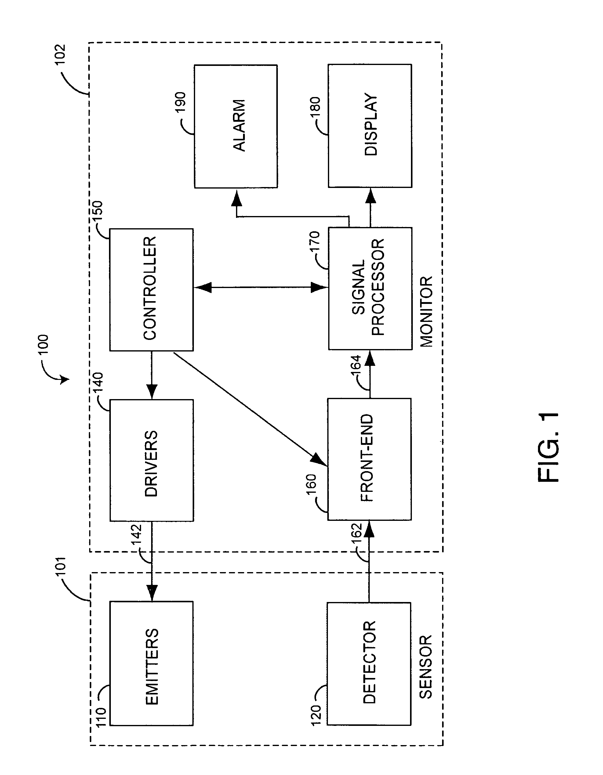
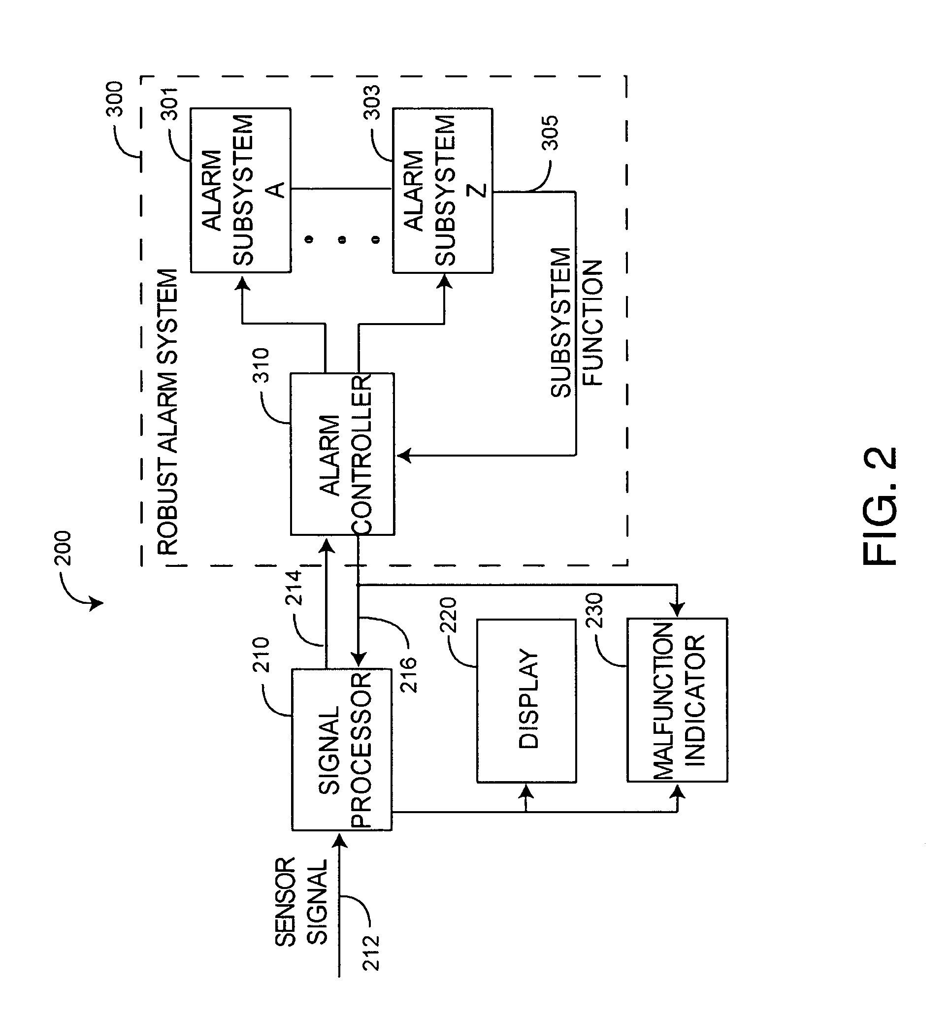
[0019]FIG. 2 illustrates a physiological measurement system 200 having a robust alarm system 300. The physiological measurement system 200 has a signal processor 210 responsive to an input sensor signal 212 and a display 220 for presenting the results. For example, the signal processor 210 may be part of a pulse oximetry monitor that is responsive to an intensity signal from an optical sensor, as described above. Likewise, the display 220 may provide a numerical indication of oxygen saturation and pulse rate calculated accordingly. Unlike a conventional alarm 190 (FIG. 1), however, the robust alarm system 300 advantageously has redundant alarms and alarm system integrity checks, as described below.

[0020]As shown in FIG. 2, the signal processor 210 inputs the sensor signal 212 and generates an alarm trigger 214 in response, such as when a parameter calculated by the signal processor is outside of predetermined limits. The alarm system 300 inputs the alarm trigger signal 214 and activ...


PUM


Abstract

A robust alarm system has an alarm controller adapted to input an alarm trigger and to generate at least one alarm drive signal in response. Alarm subsystems input the alarm drive signal and activate one or more of multiple alarms accordingly. A subsystem function signal provides feedback to the alarm controller as to alarm subsystem integrity. A malfunction indicator is output from the alarm controller in response to a failure within the alarm subsystems.

Description

REFERENCE TO RELATED APPLICATION[0001]The present application claims priority benefit under 35 U.S.C. §119(e) from U.S. Provisional Application No. 60 / 726,638, filed Oct. 14, 2005, entitled “Robust Alarm System,” which is incorporated herein by reference.BACKGROUND OF THE INVENTION[0002]Physiological measurement systems employed in healthcare often feature visual and audible alarm mechanisms that alert a caregiver when a patient's vital signs are outside of predetermined limits. For example, FIG. 1 illustrates a pulse oximeter, which measures the oxygen saturation level of arterial blood, an indicator of oxygen supply. A typical pulse oximetry system 100 has a sensor 101 that provides a sensor signal 162 to a pulse oximeter (monitor) 102. The sensor 101 has emitters 110 and a detector 120 and is attached to a patient at a selected fleshy tissue site, such as a fingertip. The emitters 110 transmit light having red and IR wavelengths into the tissue site. The detector 120 generates th...

Claims


Application Information

Patent Timeline
Patent Type & Authority Patents(United States)
IPC IPC(8): A61B5/1455
CPCA61B5/1455A61B5/746G08B1/08G08B13/1966G08B29/10A61B5/14552A61B5/1495A61B5/7405G08B25/009A61B2562/0238
Inventor KIANI, MASSI JOSEPH E.DIAB, MOHAMED KHEIRLAMEGO, MARCELO M.
Owner JPMORGAN CHASE BANK NA
Why Eureka
Try Eureka