Method and system for determining the location of a medical instrument relative to a body structure

a technology applied in the field of method and system for determining the location of a medical can solve the problems of not being able to directly detect the location of a part of an instrument relative to a body structure, only being detected with significant difficulty, and unable to determine the position of hidden parts of the instrument relative to the body structur

Active Publication Date: 2011-06-14
SMITH & NEPHEW ASIA PACIFIC PTE LTD +2
View PDF26 Cites 149 Cited by
  • Summary
  • Abstract
  • Description
  • Claims
  • Application Information

AI Technical Summary

Problems solved by technology

In the field of medicine, in particular in operations, situations can arise wherein information on the location of a part of an instrument relative to a body structure cannot be directly detected, or only detected with significant difficulty.
If, for example, an instrument is introduced into a body structure and the restricted spatial conditions prohibit a marker or reference star from being attached to the instrument, then determining the position of hidden parts of the instrument relative to the body structure becomes problematic.

Method used


Image

  • Method and system for determining the location of a medical instrument relative to a body structure
  • Method and system for determining the location of a medical instrument relative to a body structure
  • Method and system for determining the location of a medical instrument relative to a body structure

Examples


Embodiment Construction

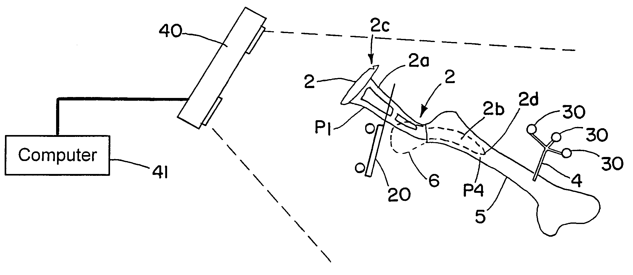
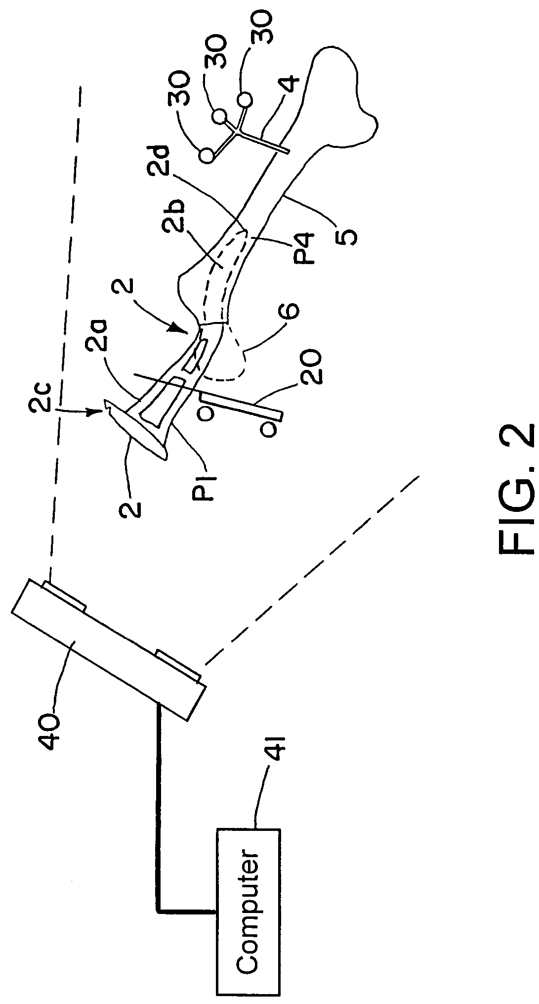
[0023]The following embodiment illustrates an exemplary implementation of the method described herein. The “bone” referred to in the present embodiment is merely one example of a body structure. The term “body structure” also includes artificial limbs, such that the method enables an instrument to be positioned relative to an artificial limbs, e.g., not necessarily during an operation.

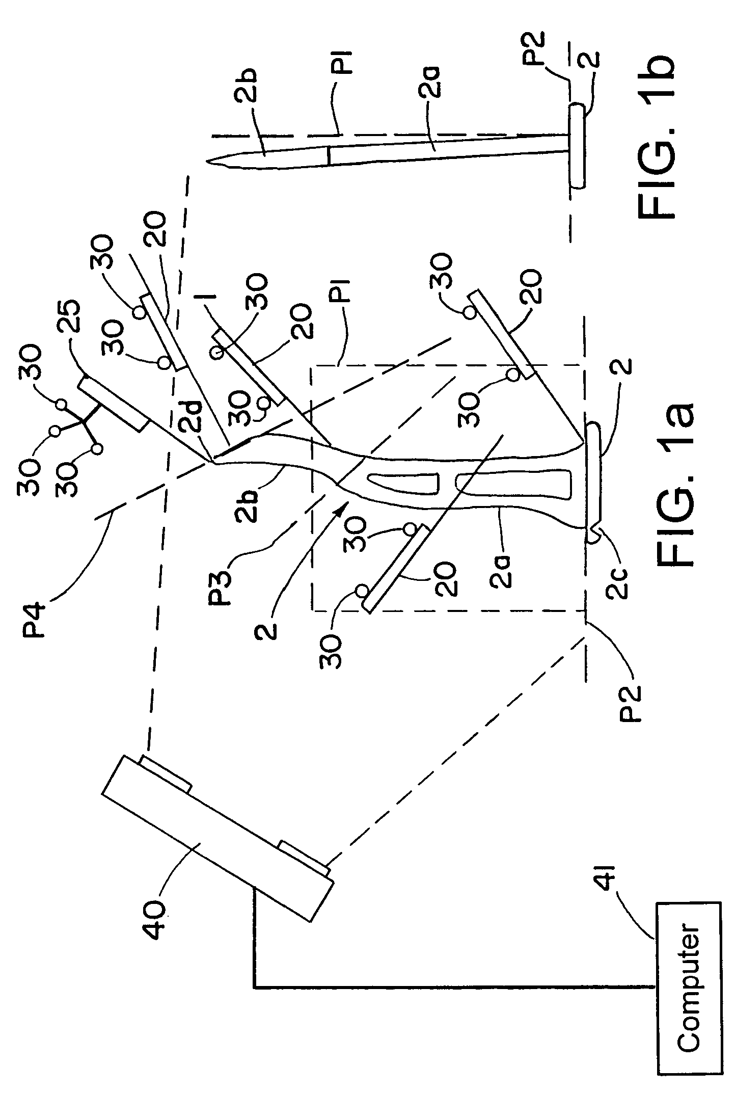
[0024]The location features of an instrument, which describe the location of parts of the instrument relative to each other, preferably are stored in advance. FIGS. 1a and 1b show a measuring assembly that enables the location features (not yet stored) of an instrument 2 to be calibrated and then stored. FIG. 1b shows a lateral view of FIG. 1a.

[0025]The instrument 2 shown in FIGS. 1a and 1b is a two-part instrument and includes two elements, a first element 2a and a second element 2b. The elements 2a and 2b can be formed as one piece or separate pieces. More particularly, the second element 2b can be ...


PUM


Abstract

A method for determining a location of an object relative to a body structure includes: providing a location of a first part of the object relative to a second part of the object, said second part different from said first part; attaching a marker device to the body structure; detecting a location of the marker device relative to the body structure; positioning the object relative to the body structure; detecting a location of the first part of the object relative to the marker device; and calculating a relative location of the second part of the object relative to the location of the body structure based on the location of the first part relative to the second part, the location of the marker device relative to the body structure, and the location of the first part relative to the marker array.

Description

RELATED APPLICATION DATA[0001]This application claims priority of U.S. Provisional Application No. 60 / 822,713 filed on Aug. 17, 2006, which is incorporated herein by reference in its entirety.FIELD OF THE INVENTION[0002]The present invention relates to a method and system for determining the location of a medical instrument relative to a body structure.BACKGROUND OF THE INVENTION[0003]Determining a location of a first object relative to a second object enables a position of the first object (e.g., a medical instrument) that is partially in the second object (e.g., a body structure such as a bone) to also be determined. In the field of medicine, in particular in operations, situations can arise wherein information on the location of a part of an instrument relative to a body structure cannot be directly detected, or only detected with significant difficulty. If, for example, an instrument is introduced into a body structure and the restricted spatial conditions prohibit a marker or r...

Claims


Application Information

Patent Timeline
Patent Type & Authority Patents(United States)
IPC IPC(8): A61B5/055
CPCA61B19/5244A61B19/52A61B17/1604A61B19/50A61B2019/5268A61B2019/5255A61B34/10A61B34/20A61B90/36A61B2034/2055A61B2034/2068
Inventor TUMA, GREGOR
Owner SMITH & NEPHEW ASIA PACIFIC PTE LTD
Why Eureka
Try Eureka