Louvre window system

a window system and louvre technology, applied in the field of louvre systems, to achieve the effect of eliminating any flexing of the joint, reducing the bending force of the rivet, and increasing the strength of the join

Inactive Publication Date: 2011-06-21
BREEZWAY AUSTRALIA
View PDF14 Cites 15 Cited by
  • Summary
  • Abstract
  • Description
  • Claims
  • Application Information

AI Technical Summary

Benefits of technology

Suitably, the at least one drainage or collection chamber has an open bottom and forms a closed chamber with the U-shaped channel to which the end clip is attached when the clip is in the closed position. This reduces the weight of the end clip and can also reduce the load placed on the louvre operating system by not having a closed bottom wall that may frictionally rub against the U-shaped section. However, if an entirely closed chamber is considered desirable it will form part of the present invention.
The handle may be connected to a link that is contained in a slot in the handle at the joint between link and handle. This enables the rivet to be supported (or fixed) to both sides of the slot in the handle. This minimizes any bending forces on the rivet, increases the strength of the joint (for components of the same size made from the same material); and eliminates any flexing of the joint under locking pressure as there is no component of the force at the joint acting perpendicular to acting / reacting forces at the handle / link joint.

Problems solved by technology

Previous end clips failed to provide internal drainage chambers which meant that if water did penetrate between end clips, it would simply run over the outside of the end clip and hopefully into a lower collection channel on the bottom of the louvre window.
However, this is quite unsightly and often water drips off the end clips and lands on the floor rather than passing down the various louvre blades and into the collection channel on the bottom of the louvre window.

Method used


Image

  • Louvre window system
  • Louvre window system
  • Louvre window system

Examples


Embodiment Construction

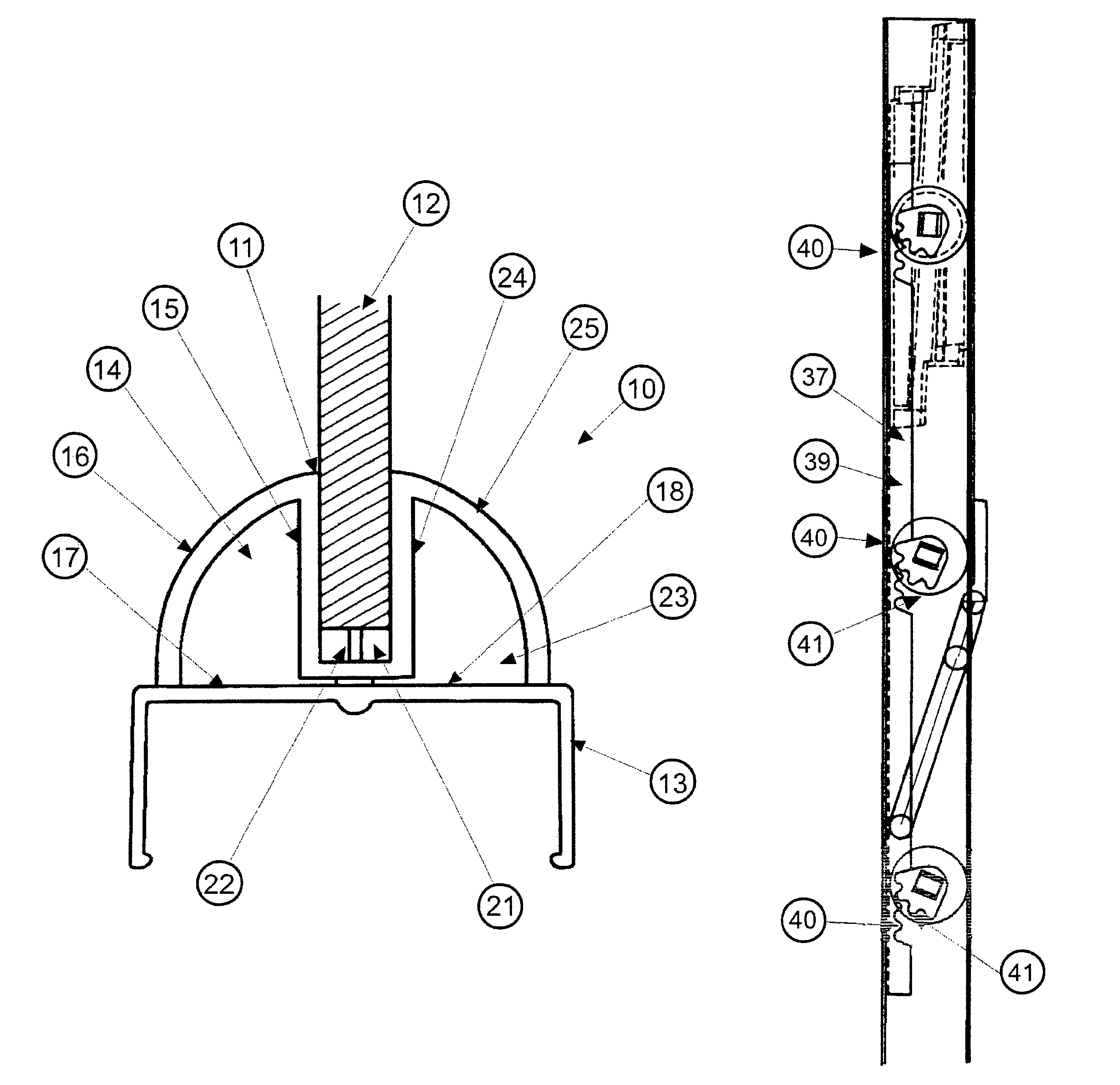
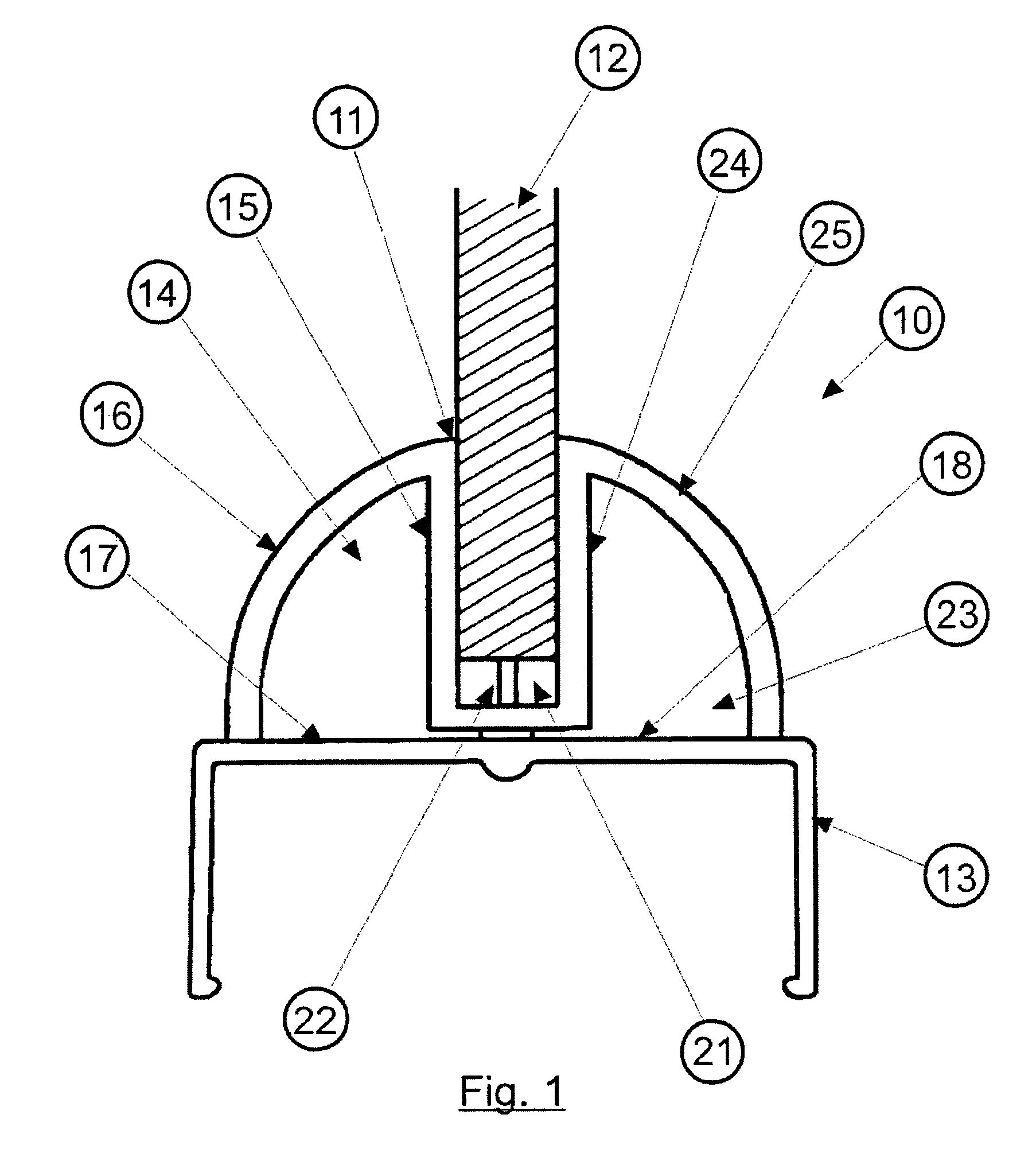
Referring to the drawings and initially to FIG. 1 there is illustrated in section view a louvre end clip 10 which is generally semicircular in configuration and contains a longitudinal recess 11 into which the edge of a louvre blade (typically a glass louvre blade) 12 can fit. End clip 10 is positioned on a channel member 13, which is typically an extruded U-shaped channel member, the channel member per se being known.

End clip 10 has a unique curved configuration and contains at least one drainage chamber 14. Drainage chamber 14 is defined by one sidewall 15 of recess 11, and the curved outer wall 16 of end clip 10. The end clip has an open bottom 17, but when the end clip is in the closed position illustrated in FIG. 1, the outer wall 18 closes chamber 14. Of course, when the end clip is pivoted to the open position, chamber 14 is now open at the bottom 17.

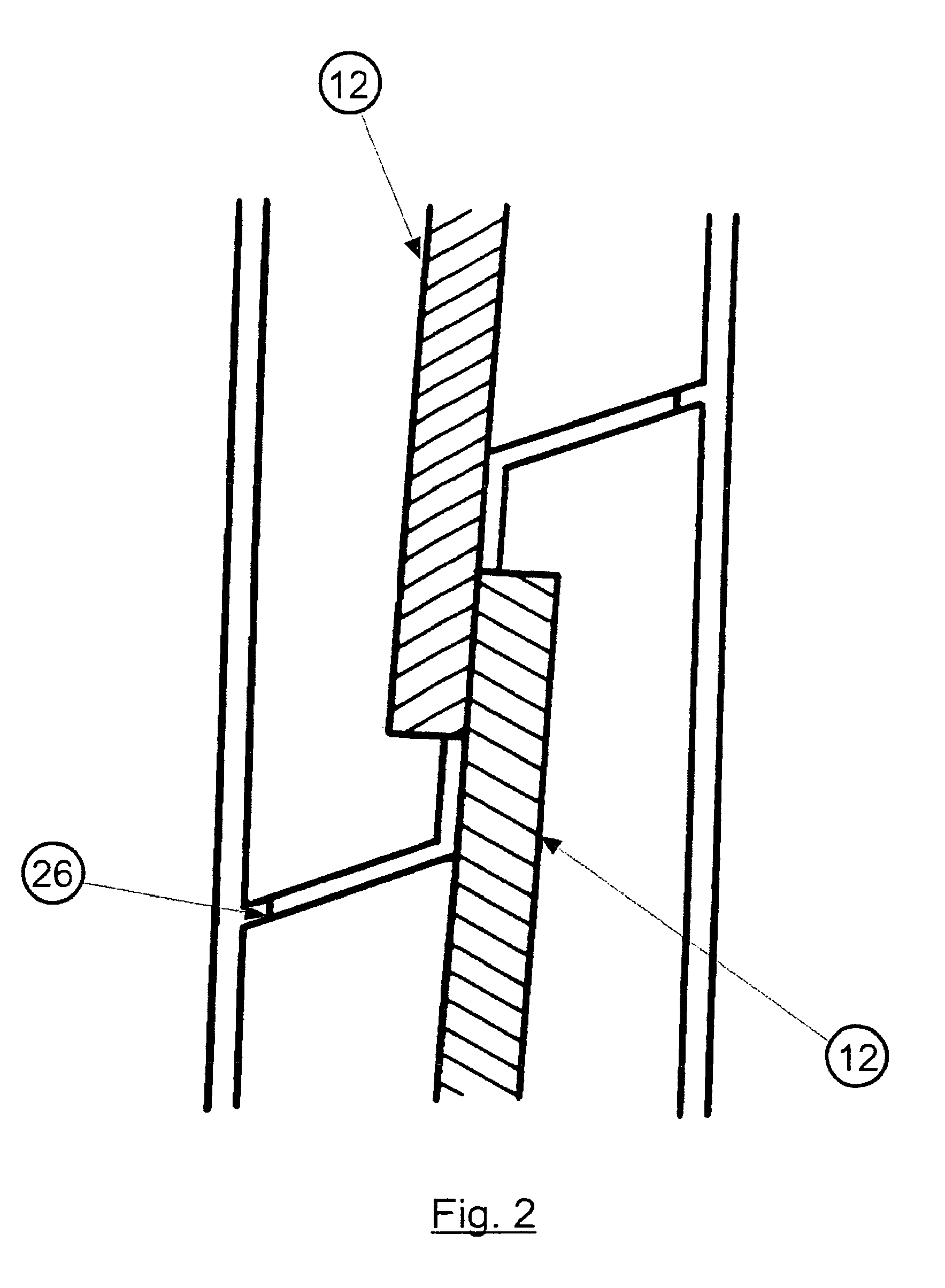
Chamber 14 extends along the length of louvre clip 10, and this is better illustrated in FIGS. 8 and 9. Chamber 14 has two end ...


PUM


Abstract

A louvre window system has an end clip (10) which is formed with at least one internal drainage channel (14) which can drain water through the end clip (10). A number of such clips can rotate between an open position and a closed position. The clips (10) are aligned when in the closed position which insures that water can drain from an upper clip through a lower clip. The clips (10) have a low friction design which enables a larger number of louvers to be rotated by a single handle (55) without placing too much load on the handle and on the louvre operating mechanism. A simple efficient louver operating mechanism (27; 37) is used to operate the end clips.

Description

FIELD OF THE INVENTIONThis invention is related to a louvre system for louvre windows, and particularly for louvre windows comprising glass, metal, timber, plastic blades etc, and comprises a plurality of improvements to existing louvre systems, these improvements being directed to improvements to reducing water penetration and to drain water from a louvre window, and improvements to the louvre operating system by which louvre blades can be opened and closed together. Other improvements to the louvre system will also become apparent.BACKGROUND ARTLouvre windows consist of a surround frame formed of upper and lower horizontal frame portions and opposed side frame portions which are fastened together. The frame supports an array of horizontal louvres which pivot about horizontal pivot pins between louvre open and louvre closed positions. It is known to tip the frame on its side such that the louvres extend vertically, however the invention will be described with respect to horizontall...

Claims


Application Information

Patent Timeline
Patent Type & Authority Patents(United States)
IPC IPC(8): E06B7/00E06B7/096E06B7/14
CPCE06B7/14E06B7/096
Inventor ALEXANDER, EDWIN JOHNALLEN, ROBERTGRIMSHAW, JOHNCHASTON, KEITH JAMES
Owner BREEZWAY AUSTRALIA
Why Eureka
Try Eureka