Control device and method for guided travel of unmanned vehicle

a technology of control device and unmanned vehicle, which is applied in the direction of process and machine control, distance measurement, instruments, etc., can solve the problems of reducing work efficiency, difficulty or may be impossible for an ordinary bulldozer b>16 to push out piles, etc., and achieves efficient performance, reduced time and cost for carrying, and efficient leveling work.

Active Publication Date: 2011-06-21
KOMATSU LTD
View PDF9 Cites 16 Cited by
  • Summary
  • Abstract
  • Description
  • Claims
  • Application Information

AI Technical Summary

Benefits of technology

[0020]The present invention has been made in view of the above circumstances and has an object to overcome the above problems and to provide a guided running control device and a method for an unmanned vehicle that can efficiently performs the leveling work at the discharge site without increasing the cost of the vehicle, and easily generate the running course in a short time and low-cost.
[0031]According to the present invention, by automatic calculation process based on the data regarding each position on the survey line 20 measured through teaching, surveying and the like, plural target discharge positions 26′ are obtained in the vicinity of and along the survey line 20, and the reference approach directions 31 normal to the survey line 20 are determined. Based on the calculation result, running courses 27 to approach each of the target discharge position 26′ in each of the reference approach directions 31 are automatically generated, and each vehicles 13 is guided to travel along each of the generated running courses 27 and discharge at each of the target discharge positions 26′. Thus, it is possible that the vehicle 13 approaches in the vicinity of the survey line with the reference discharge position 31, whereby discharging can be performed in the most efficient manner, and that the vehicle 13 discharges the earth and sand outside the survey line 20 (or in the vicinity of the survey line 20) using the high-dump work in a secure and correct manner. As a result, almost all of the earth and sand can be discharged down to the precipice outside the survey line 20, the earth and sand that remains in the discharge site 21 can be reduced as minimum as possible. Consequently, leveling work can be efficiently performed by ordinary bulldozers 16, and the cost of efficient leveling work, vehicles and the like can be dramatically reduced.
[0032]Additionally, unlike the related arts, when generating the plural running courses 27, it is not necessary to differently teach the running courses 27 to each of the target positions (discharge positions). Each of the running courses 27 is automatically generated after measuring each of the positions along the survey line 20 in the discharge range 20L. Therefore, time and cost for carrying work by the vehicle 13, preparation work (teaching or surveying) performed before the leveling work by the vehicle 16 can be reduced.
[0033]As mentioned above, according to an aspect of the present invention, leveling work at the discharge site 21 can be efficiently performed without raising the cost of vehicles, and the running courses 27 can be easily generated in a short time and at low cost.
[0034]Additionally, according to the fourth and fifth aspect of the present invention, the earth and sand can be discharged outside the survey line 20 in a safety and secure manner without derail and the like of vehicle 13. Thus, it is possible to safely perform the guided travel of the vehicle 13, and operate the discharge work safely.

Problems solved by technology

Therefore, it is difficult or may be impossible for an ordinary bulldozer 16 to push out the pile 26c.
And, the amount of discharge work may exceed the capability of leveling work, resulting in decreased work efficiency.
Furthermore, to enhance the capability of leveling work, it is necessary to use a larger bulldozer 16, strengthen the pulling power, or increase the number of the bulldozers 16, which may lead to increase in cost of the vehicles.
As mentioned above, the related art 1, however, requires time or cost for the teaching work on a running course, thus there remains a problem that time or cost required for generating the running course increases.

Method used


Image

  • Control device and method for guided travel of unmanned vehicle
  • Control device and method for guided travel of unmanned vehicle
  • Control device and method for guided travel of unmanned vehicle

Examples


Embodiment Construction

[0047]Hereinbelow, an exemplary embodiment of a control device for a guided travel of a vehicle according to the present invention will be described in detail with reference to the attached drawings.

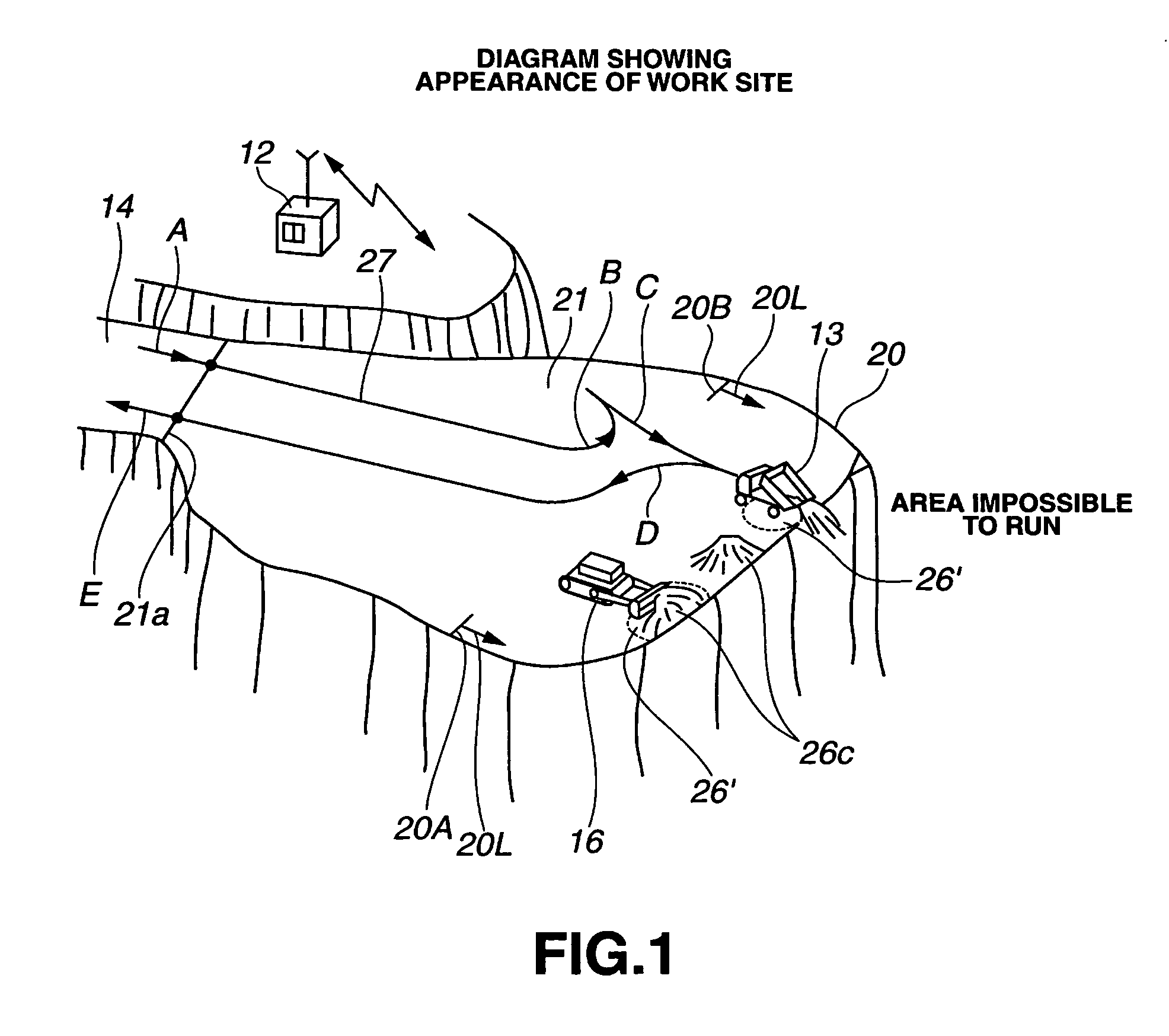
[0048]FIG. 1 shows an appearance of a work site of the exemplary embodiment. In this exemplary embodiment, a case is assumed where the guided travel of the unmanned vehicle 13 such as an off-road dump truck, which loads earth and sand, is performed along a running course 27 to a target discharge position 26′ in a discharge site 21 in a large scale mine site, and the earth and sand is discharged at the target discharge position 26′.

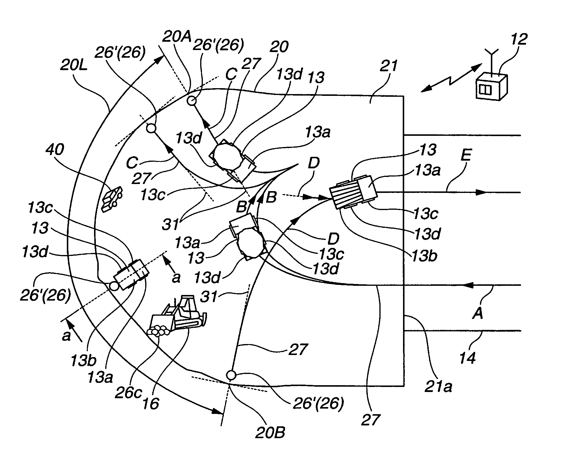
[0049]FIG. 3 is a conceptual diagram of the discharge site 21 viewing from above.

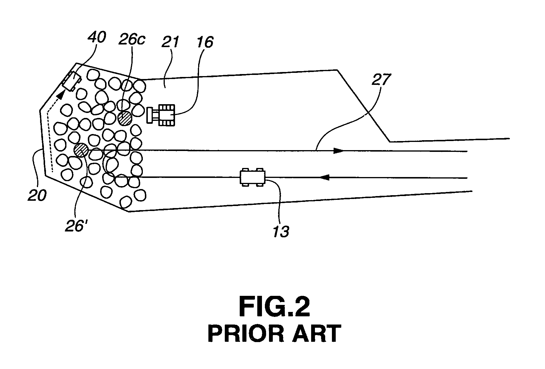
[0050]In this exemplary embodiment, a case is assumed where a discharge range 20L (end points: 20A, 20B) is determined from a survey line 20 that is a boundary line of the discharge site 21, a guided travel of vehicles 13 is performed along running courses 27 to each of the target ...


PUM


Abstract

Leveling operation can be effectively performed at a discharge site without increasing a cost of vehicles, and a running course can be easily generated in a short time and at a low-cost. Based on each of measured position data of a survey line 20 of a discharge site 21, a normal line Lc normal to the survey line 20 is obtained, a target discharge position 26′ is positioned at a prescribed distance away from the survey line 20 in an inward direction of the discharge site 21 based on the normal line Lc, and then data of a running course 27 in which a reference approach direction 31 to approach the target discharge position 26′ is a direction normal to the survey line 20 are generated.

Description

TECHNICAL FIELD[0001]The present invention relates to a control device and a method for a guided travel of an unmanned vehicle, more particularly to a preferred device and a method for applying to a case where, in a discharge site in a mine and the like, a guided travel of an unmanned vehicle is performed to a target discharge position and earth and sand is unloaded.BACKGROUND ART[0002]In a large mine, a guided travel system for an unmanned vehicle in which the unmanned vehicle such as unmanned off-road dump trucks is guided and travels has been widely used in order to reduce painful works, decrease the production cost, and save the fuel.[0003]The above-mentioned unmanned vehicle has a position measuring device that measures its running position using GPS (Global Positioning System) and the like. Additionally, a monitor station that monitors plural unmanned vehicles obtains, by surveying a work site or teaching, position data on a running course through which the unmanned vehicle is...

Claims


Application Information

Patent Timeline
Patent Type & Authority Patents(United States)
IPC IPC(8): G01C22/00
CPCG05D1/0272G05D1/0282G05D1/0278G05D2201/0202
Inventor SUDOU, TSUGIOTOJIMA, MASANORITAKEDA, KOJINISHIJIMA, AKIHARUMORI, MASAKIOZAKI, TOMONORIKUROMOTO, KAZUNORI
Owner KOMATSU LTD
Why Eureka
Try Eureka