Spliced long-length hose and method for splicing hoses

a technology of splicing hoses and hoses, which is applied in the direction of hose connections, flexible pipes, rigid pipes, etc., can solve the problems of not being able to lay such lines, the situation is often worse, and the formation of at least three potential leakage paths in the coupled hoses, so as to reduce the pressure bearing capacity of the hose-line, the length of the built-in rigid section is minimal, and the effect of simple production

Active Publication Date: 2011-06-28
PHOENIX RUBBER GUMIIPARI KFT SZEGED
View PDF16 Cites 1 Cited by
  • Summary
  • Abstract
  • Description
  • Claims
  • Application Information

AI Technical Summary

Benefits of technology

[0013]The object of the invention is therefore to eliminate the above disadvantages by coupling the hose-pieces so that, according to the recognition of the invention, the liner remains continuous, thus there is no potential leakage path and the length of the built-in rigid section is minimal, the bond is still complete without reducing the pressure bearing capacity of the hose-line. At the same time the design according to the invention does not require complicated, expensive bonding elements and can be produced in a simple way. The design according to the invention can be used also for vulcanized rubber hoses, hoses with thermoplastic or cross-linked plastic liner, and unbonded plastic hoses containing reinforcing plies.

Problems solved by technology

When hoses are connected to each other, the common disadvantage of the above referred designs is that at least three potential leakage paths can be formed in the coupled hose-lines; namely between the two couplings connected to each other, and between the corresponding metal couplings and the elastic liner.
The actual situation is often worse than this, because usually the coupling device itself consists of two or more parts and leakage can be developed between these parts too.
The above detailed disadvantages can explain the reluctance of the users to couple hoses into lines or the fact for example that laying of such lines is often not allowed in the case of high-pressure submarine lines for reasons of environment protection.
Another considerable disadvantage is that at the location of the connection a relatively long, rigid section is formed, the dimension of which corresponds to that of the two couplings, and during the use this makes difficult or impossible to wind the hoses to a reel of reasonable size.

Method used


Image

  • Spliced long-length hose and method for splicing hoses
  • Spliced long-length hose and method for splicing hoses
  • Spliced long-length hose and method for splicing hoses

Examples


example 1

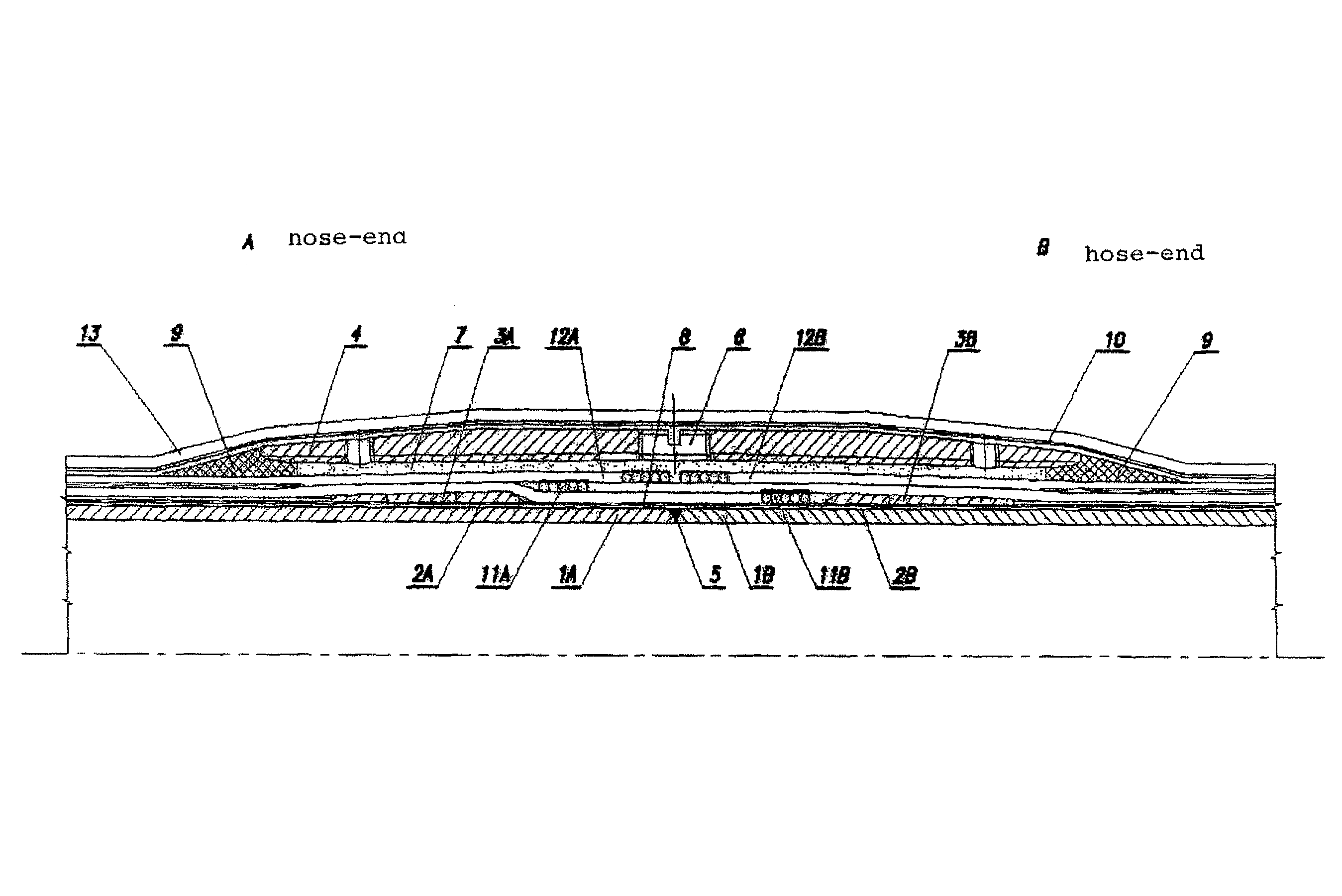
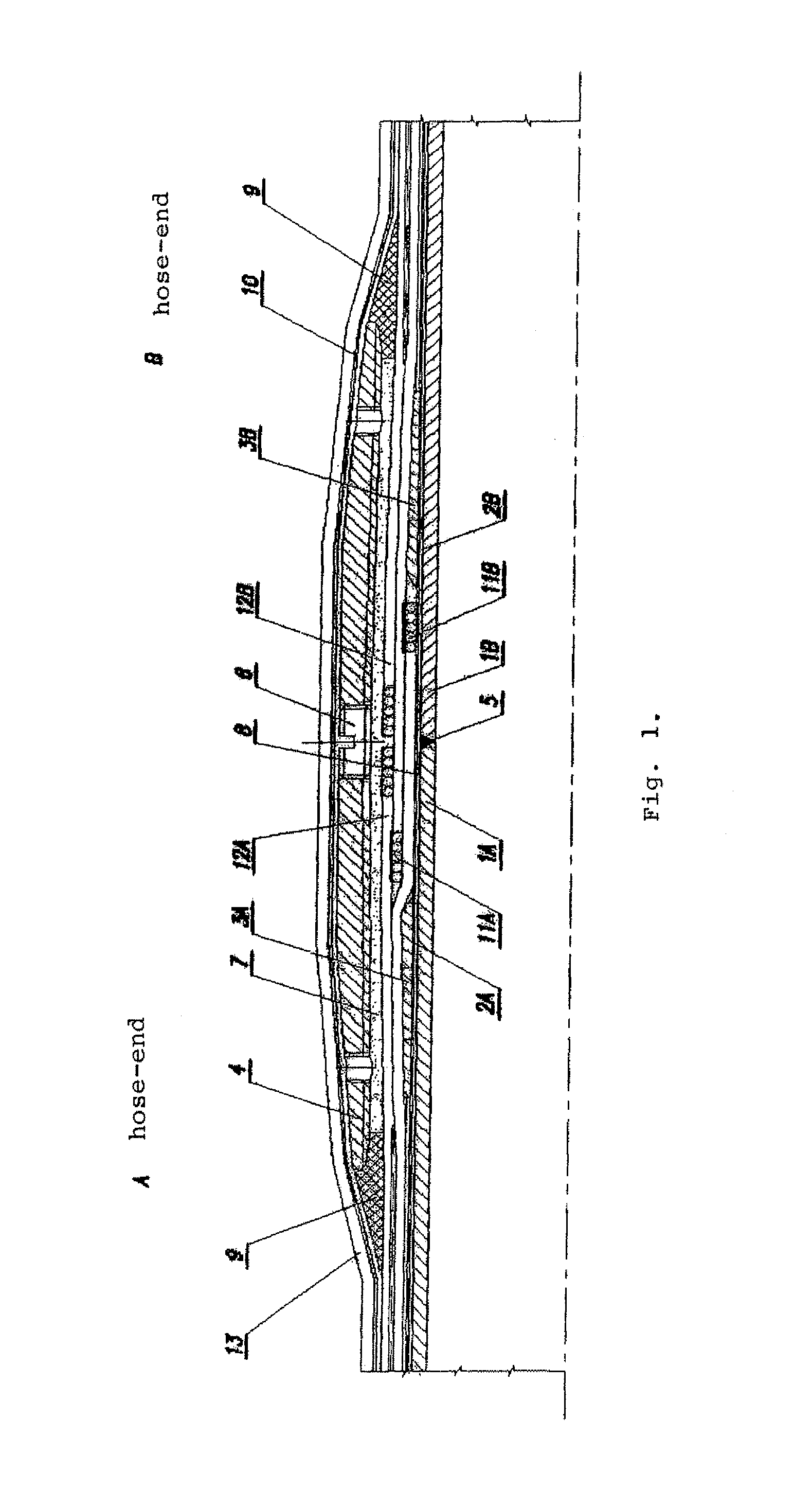
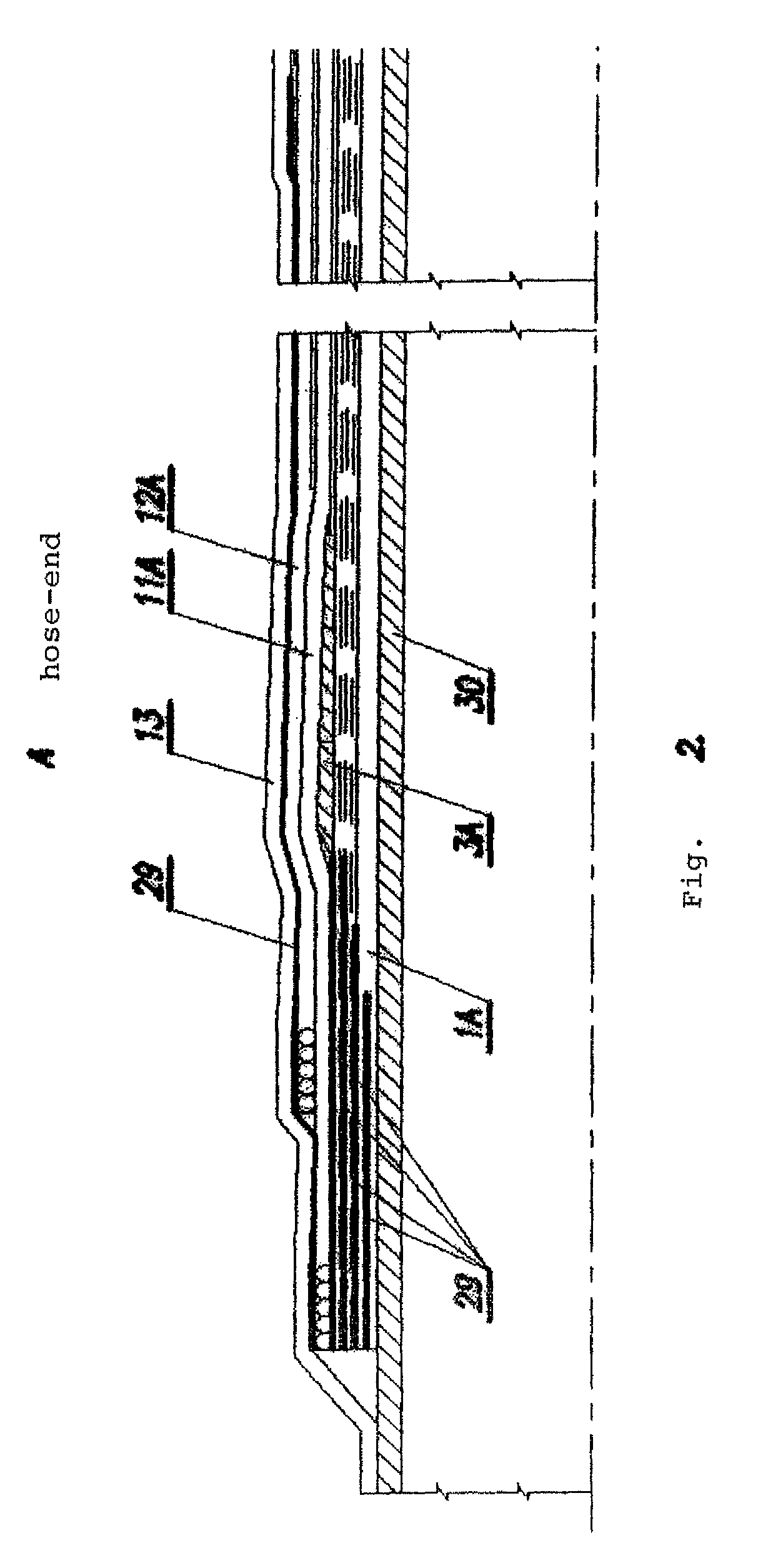
[0042]Two rubber hoses with an inner diameter of 76 mm were built up. The hose liner 1 (liquid sealing layer) was made of rubber compound containing NBR. Load-distributing rubberized textile layers 2 were arranged above the liner. The hoses contained two reinforcing plies (cables) 11 and 12. A 70 mm long spiral cone 3 having a wall thickness increasing gradually from the direction of the hose-body up to 3.6 mm is built in under said reinforcing plies at the location of the splicing. The hoses were vulcanized on hose mandrel. The conical rigid outer sleeve 4, made of steel in this case, with an inner diameter flaring in an angle of 1° to the central point and with an inner surface formed circularly corrugated was pulled onto hose A. The splicing was carried out on hose mandrel, liner-ends 1A, 1B, were spliced with uncured rubber compound 5, and load-distributing rubberized textiles 2A, 2B were joined by using unvulcanized load-distributing textile 8 after folding back the reinforcing...

example 2

[0044]Bonded rubber hoses with four cable plies were spliced. The spliced section is shown in FIG. 3. The hoses had an inner diameter of 103.5 mm. The innermost layer of the hoses was an inner flexible stripwound 25 of stainless steel ending in a threaded sleeve 26. At the end of hose A there was a right-hand thread, at the end of hose B there was a left-hand thread. The hoses contained liquid sealing layer, liner 1, made of rubber compound based on synthetic rubber. Load-distributing rubberized textile layers 2 were placed above the liner 1. A spiral cone 3 with a length of 135 mm and with a wall thickness increasing gradually from the direction of the hose-body up to 4 mm is built in under the cables at the location of the to-be splicing. The upper (third and fourth) reinforcing cable plies 28A, 28B were bound at a distance of 20 mm from the inner end of the spiral cone 3 and the excess was cut. The hoses were vulcanized on hose mandrel. The conical rigid outer sleeve 4, made of s...

example 3

[0045]By means of FIG. 4 splicing of unbonded hoses with plastic liner and reinforced with steel profile 15, lower (first) flat steel ply 16, and upper (second) flat steel ply will be described. Distinction is made between hose A and hose B to be spliced. Plastic covers 24 of the hoses are cut back in a length as necessary. Fixing element 18, gullet-tooth fixing element, fixing element 20, and O-rings 21 protecting against outer moisture penetration are pulled onto the two hose-ends. Outer sleeve 22 is pulled onto one of the hoses. Flat steel plies 16, 17 are folded back. Steel profiles 15A, 15B and liners 1A, 1B are cut back on either hose by half of the intended overlapping of the flat steel plies 16, 17. The steel profile 15 is loosed and an inner sleeve 14 is pulled onto one of the hoses. The liner-ends 1A, 1B are welded. The inner sleeve 14 is pulled onto the welded liner, then steel profiles 15A, 15B are laid back from either side. The upper flat steel ply 16A of hose A, then ...


PUM


Abstract

A long-length hose spliced from two or more hoses containing an inner sealing layer, at least two spirally laid reinforcing plies, and a cover. A liner forming the inner sealing layer is formed by leak-tight splicing of liners of hoses to be spliced and the reinforcing plies are embedded into filling / adhesive material inside of a rigid outer sleeve, at the location of the splicing.

Description

RELATED APPLICATIONS[0001]This application claims foreign priority benefits under 35 U.S.C. 119 of Hungarian Patent Application No. P 06 00676, filed on Aug. 24, 2006 in Hungary, the entire disclosure of which is incorporated herein by reference.FIELD OF THE INVENTION[0002]The invention relates to spliced long-length hose-line and method for splicing the hoses forming it. The long-length hose-line according to this invention is spliced from two or more hoses and contains at least two reinforcing plies. Further, the term “long-length” used in the Description and Claims of the present invention typically means that the length of the hose exceeds the hundredfold of its internal diameter. The splicing method of the hose-pieces is also within the scope of the invention.BACKGROUND OF THE INVENTION[0003]It is known that high-pressure hoses containing various metal reinforcing plies are widely used by the industry in different fields. These hoses are usually characterized by a polymer-based...

Claims


Application Information

Patent Timeline
Patent Type & Authority Patents(United States)
IPC IPC(8): F16L11/00
CPCF16L31/02F16L31/00
Inventor NAGY, TIBORKATONA, TAMASDOMONKOS, IMRENACSA, LASZIOGORGENYI, PETERLANTOS, ELEMER
Owner PHOENIX RUBBER GUMIIPARI KFT SZEGED
Why Eureka
Try Eureka