Compensation of beamforming errors in a communications system having widely spaced antenna elements

a technology of antenna elements and beamforming errors, applied in the field of communication systems, can solve problems such as the difficulty of properly concerting the actions of various components

Inactive Publication Date: 2011-06-28
HARRIS CORP
View PDF41 Cites 11 Cited by
  • Summary
  • Abstract
  • Description
  • Claims
  • Application Information

AI Technical Summary

Problems solved by technology

However, as the dimensions of the array, the number of antenna elements, and the precision required in certain beamforming applications increases, properly concerting the actions of the various components becomes increasingly difficult.

Method used


Image

  • Compensation of beamforming errors in a communications system having widely spaced antenna elements
  • Compensation of beamforming errors in a communications system having widely spaced antenna elements
  • Compensation of beamforming errors in a communications system having widely spaced antenna elements

Examples


Embodiment Construction

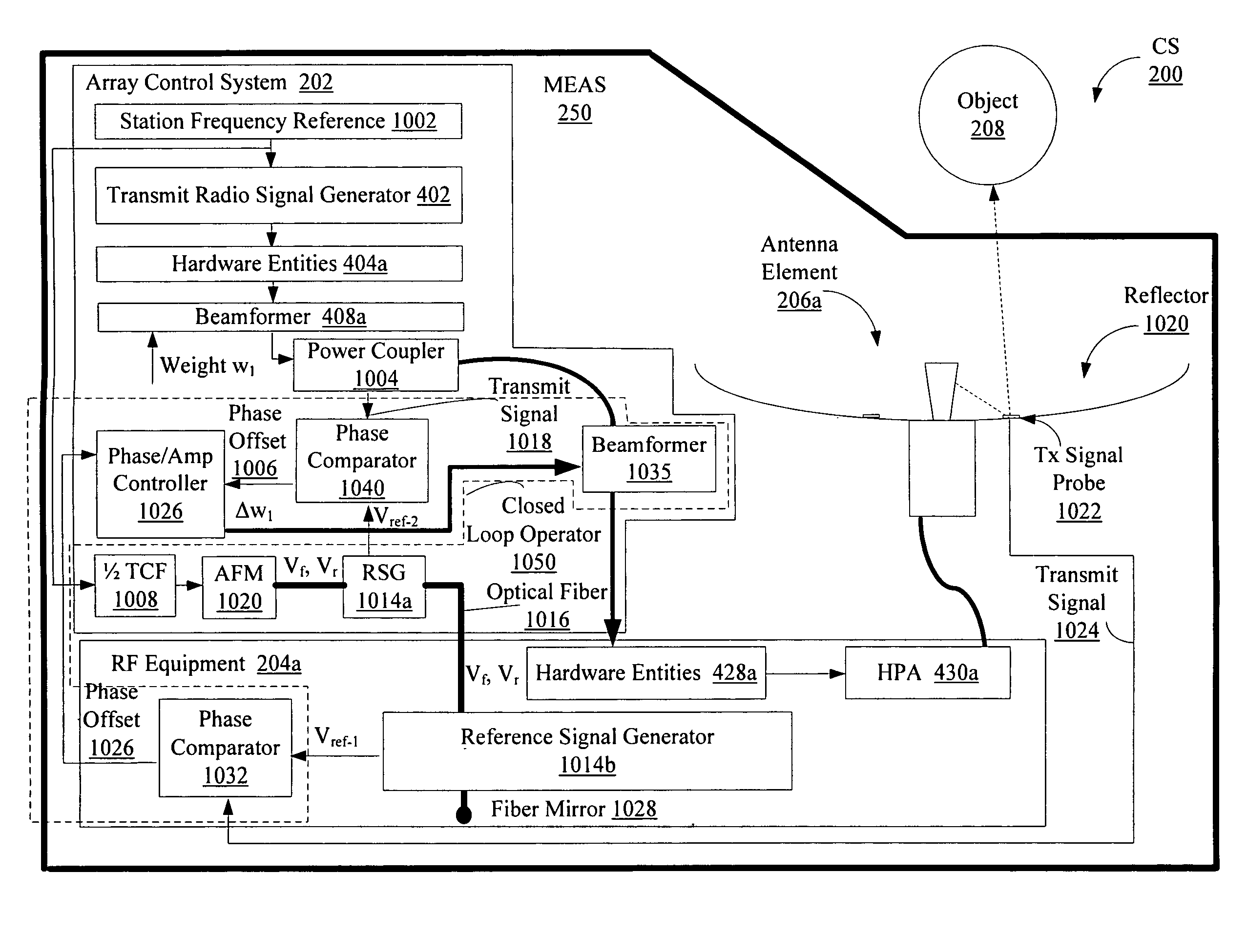
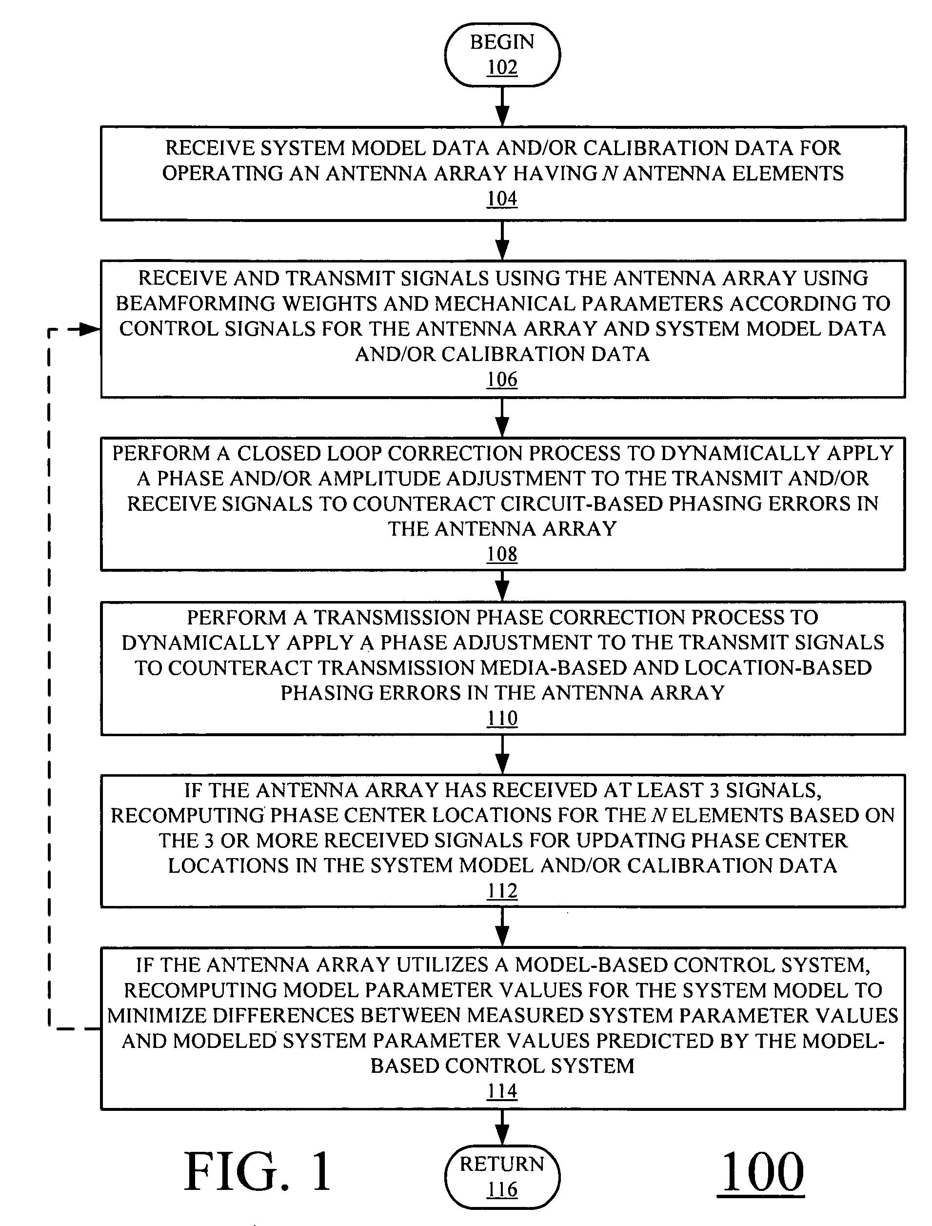
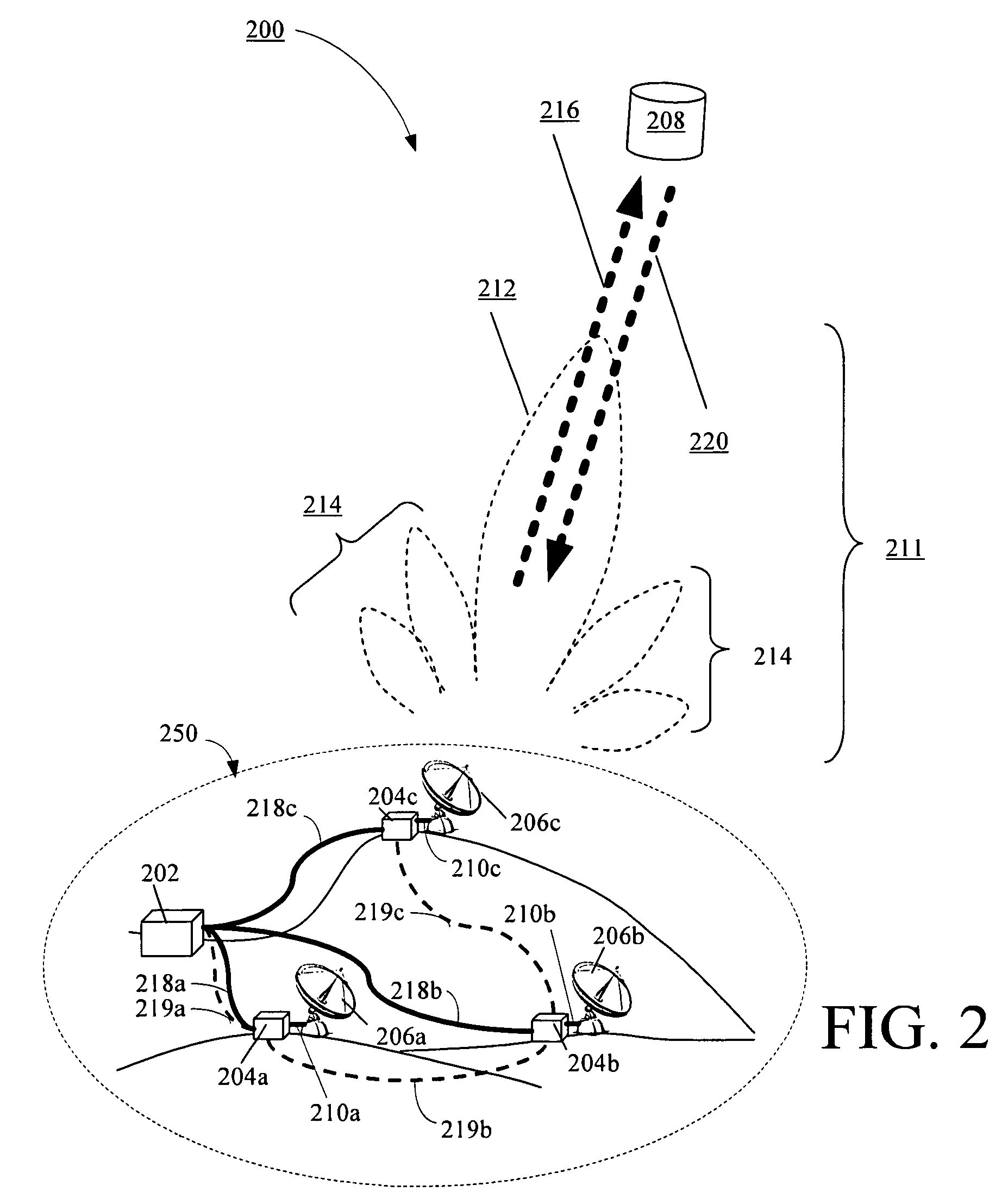
[0029]The present invention is described with reference to the attached figures, wherein like reference numerals are used throughout the figures to designate similar or equivalent elements. The figures are not drawn to scale and they are provided merely to illustrate the instant invention. Several aspects of the invention are described below with reference to example applications for illustration. It should be understood that numerous specific details, relationships, and methods are set forth to provide a full understanding of the invention. One having ordinary skill in the relevant art, however, will readily recognize that the invention can be practiced without one or more of the specific details or with other methods. In other instances, well-known structures or operations are not shown in detail to avoid obscuring the invention. The present invention is not limited by the illustrated ordering of acts or events, as some acts may occur in different orders and / or concurrently with o...


PUM


Abstract

Systems and methods for operating a communications system. The methods involve computing one or more complex weights to be applied to transmit signals and receive signals by beamformers. The complex weights are based at least on configuration data for the communications system. The methods also involve applying a first plurality of weight corrections to the complex weights based on phasing errors occurring in a communication path inclusive of a control system and antenna elements. The methods further involve applying a second plurality of weight corrections to the complex weights based on phase differences at the antenna elements relative to a reference location for the receive signals.

Description

BACKGROUND OF THE INVENTION[0001]1. Statement of the Technical Field[0002]The invention concerns communications system. More particularly, the invention concerns systems and methods for compensation of beamforming errors in a communications system having widely spaced antenna elements.[0003]2. Description of the Related Art[0004]Multiple element antenna arrays are widely used in wireless communications systems to enhance the transmission and reception of signals. In particular, the enhanced performance is generally provided by using such antenna arrays in conjunction with beamforming techniques. Conventional beamforming takes advantage of interference between electromagnetic waves generated by each of the different antenna elements in the antenna array to change the overall directionality for the array. For example, during transmission, the phase and relative amplitude of the transmitted signal at each antenna element is adjusted, in order to create a desired pattern of constructive...

Claims


Application Information

Patent Timeline
Patent Type & Authority Patents(United States)
IPC IPC(8): H01Q3/26H01Q3/34
CPCH01Q1/246H01Q3/26H04B17/21H04B7/0617H04B7/0848H01Q3/267
Inventor MARTIN, G. PATRICKMINEAR, KATHLEENROACH, JOHNDIANIC, ALLAN V.ADAMS, JR., WILLIAM C.RALSTON, LYNDA MARGARET
Owner HARRIS CORP
Why Eureka
Try Eureka