
Method for communication on a multidrop bus of a magnetic resonance system

Inactive Publication Date: 2011-06-28
SIEMENS HEALTHCARE GMBH
View PDF20 Cites 0 Cited by
  • Summary
  • Abstract
  • Description
  • Claims
  • Application Information

AI Technical Summary

Benefits of technology

The present invention provides a method for communication on a multidrop bus of a magnetic resonance system using an adaptive protocol for telegrams on a multipoint bus. The method uses an adaptive protocol script for telegrams on a multipoint bus, which allows devices using different communication protocols to be co-present on the bus and conduct multipoint communication with a main control unit. The method includes a link layer and a service layer, with the link layer responsible for distinguishing addresses and frame types and the service layer responsible for providing interfaces that are independent of the communication protocols used by the various devices. The method also includes a series of insertion and extraction operations to produce and analyze the telegrams, as well as a checking and matching process to recognize different regulators and effect frame state binding on the basis of the frame type composite telegram. The technical effects of the invention include improved communication on the multidrop bus and improved efficiency in processing telegrams.

Problems solved by technology

When there are different monitoring target circumstances, separate management using independent monitoring units is usually conducted in the system, since the monitored parameters needed for different monitoring targets vary, but there are the following drawbacks in this type of system:It is difficult to obtain monitoring units possessing similar functions, and the system requires that many modules be managed, so making the cost high;the increase of the modules leads to an increase of the complexity of failure modes, and so the cost of investigations into failure mode analysis (Failure Mode and Effects Analysis, FMEA), is increased;the increase of hardware lowers the reliability of interrelations between components, and increases the hardware failure rate, so leading to a reduction of the mean time between failure (MTBF); andsince the communication protocols of the components of different companies differ, it is not possible to interconnect identical interfaces using a single bus, and it is difficult to achieve integration and embedding.
Since different monitoring points are necessarily subject to differences of monitoring parameter characteristics, the use of such independent monitoring modules has the following drawbacks:High precision needs to be used for all the regulators (or monitoring units), and costs are very high;some monitoring points are under quite highly sensitive control, and it is difficult to conduct work in coordination with other channels;it is difficult for the functions of regulators (or monitoring units) to keep up with the technological innovations of products, and it is necessary to use new types of regulators (or monitoring units) in order to adapt to rapid edition upgrades; andthe type selection range for the regulators (or monitoring units) is small, and it is difficult to keep pace with the supply of spares and changes in commercial supplies.
In some magnetic resonance systems a regulator (or monitoring unit) offline operation arrangement is used in order to avoid the above two drawbacks, but there are the following problems in such a system:The regulators (or monitoring units) are not connected to the system and, in abnormal circumstances, it is not possible to ascertain in real time whether parameter changes have affected the image quality;it is not possible for system maintenance staff to conduct highly efficient inspection and measurement work.
There are also some systems in which, in order to avoid the above drawbacks, bus communication is not used, and a communication mode with arrival points reaching monitoring units at many points is used for regulators (or monitoring units), but there are still some problems with such a system:The large number of physical connections increases the cost of the hardware; andthe large number of physical connections increases the hardware failure rate and reduces the mean time between failure.

Method used


Image

  • Method for communication on a multidrop bus of a magnetic resonance system
  • Method for communication on a multidrop bus of a magnetic resonance system
  • Method for communication on a multidrop bus of a magnetic resonance system

Examples


Embodiment Construction

[0035]The telegrams of a variety of mainstream ASCII-coded centralized communication regulators (or monitoring units) all use start characters to bind unit address formats. The present invention's adaptive protocol script for telegrams on a multidrop bus of a magnetic resonance system (Adaptive Protocol Script For Telegram Over Multidrop Bus, abbreviated below to APSTOMB) resolves adaptation problems by means of start character and main address binding for frame types, makes it possible for regulators (or monitoring units) which use a variety of different protocols to work together, and achieves multipoint communications.

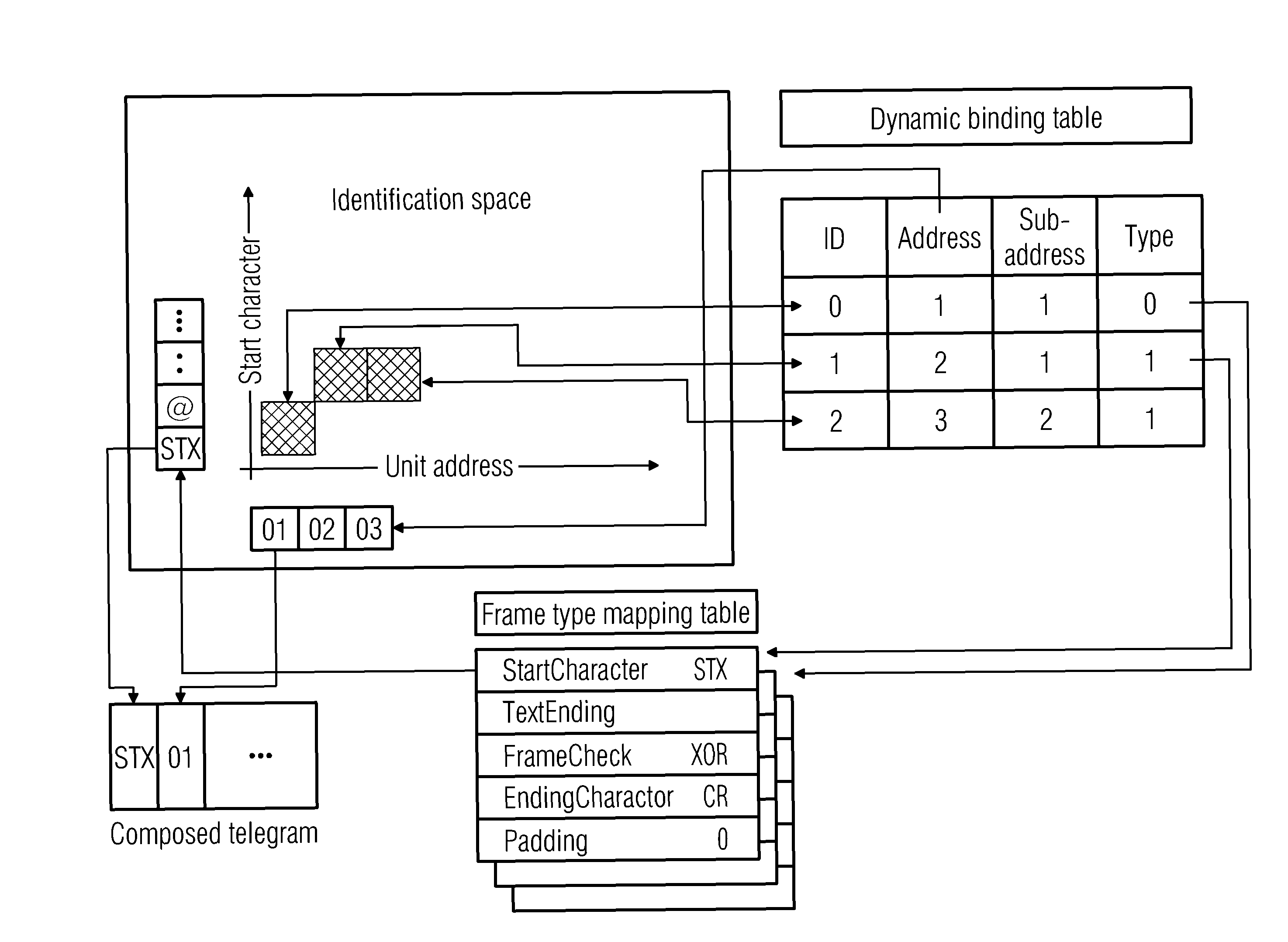
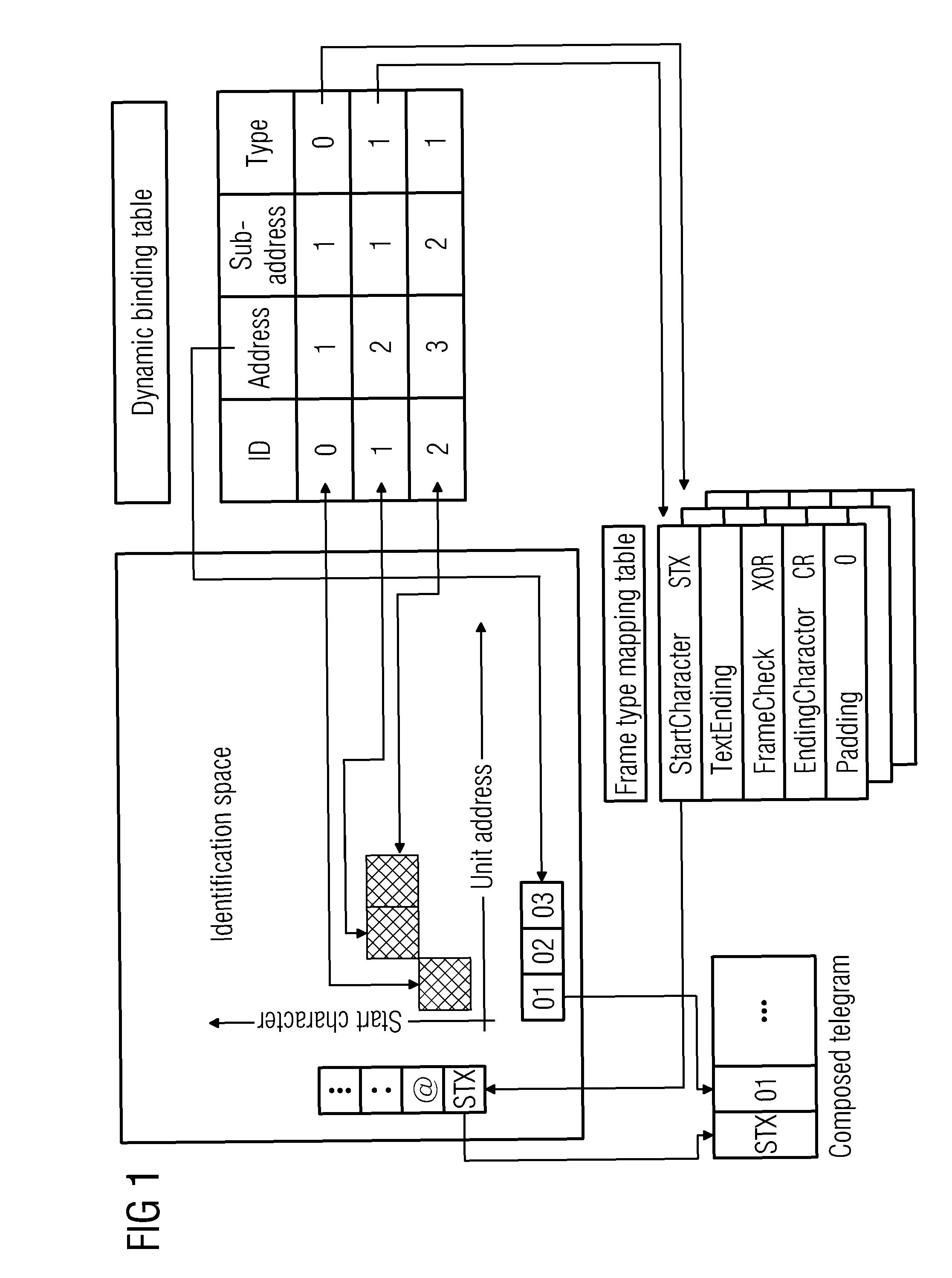
[0036]Referring to FIG. 1, this shows the use of “start character+address+frame type” binding to effect mapping. In the drawing, the cross-hatched squares in the identification space correspond to the personal identification (ID) of a regulator (or monitoring unit) dynamic binding table. The dynamic binding table here is a search table which is maintained by softwar...


PUM


Abstract

In a method of communication on a multidrop bus of a magnetic resonance system, an adaptive protocol script for telegrams on the multidrop bus is used, that implements adaptive protocol matching using telegram start characters, addresses and frame-type binding. For this purpose, a telegram frame is divided into a link layer and a service layer, the link layer being device-based and being responsible for differentiating addresses and frame types, and enabling devices that use different communication protocols to be simultaneously present on the bus. The service layer represents the load of the link layer, and its service script is operation-based, and the service layer provides, for the exterior, interfaces that are independent of the communication protocols used by the devices.

Description

BACKGROUND OF THE INVENTION[0001]1. Field of the Invention[0002]The present invention relates to a method of communication on a multidrop bus of a magnetic resonance system, and, more particularly, it relates to a multidrop bus telegram adaptive protocol script (Adaptive Protocol Script For Telegram Over Multidrop Bus, abbreviated below to APSTOMB) communication method which is used in a magnetic resonance system.[0003]2. Description of the Prior Art[0004]Currently, in order to strictly maintain the operating environment of a scanner in a permanent-magnet magnetic resonance system, the usual practice is that many control channels or monitoring channels are used to effect regulation and state monitoring of physical parameters such as the magnet temperature, etc. for a monitoring target.[0005]When there are different monitoring target circumstances, separate management using independent monitoring units is usually conducted in the system, since the monitored parameters needed for diff...

Claims


Application Information

Patent Timeline
Patent Type & Authority Patents(United States)
IPC IPC(8): G06F13/42H04L69/40
CPCH04L69/18H04L69/26H04L2012/4026
Inventor LIN, JIA YU
Owner SIEMENS HEALTHCARE GMBH
Learn More