
Baluster system and method

a technology of stairways and balusters, applied in the field of stairway balusters, can solve the problems of difficult removal of balusters which are oftentimes installed with the use of nails, screws, adhesives, etc., and achieve the effect of easy attachment of balusters and aesthetics of balusters

Active Publication Date: 2011-07-05
S V INT
View PDF56 Cites 24 Cited by
  • Summary
  • Abstract
  • Description
  • Claims
  • Application Information

AI Technical Summary

Benefits of technology

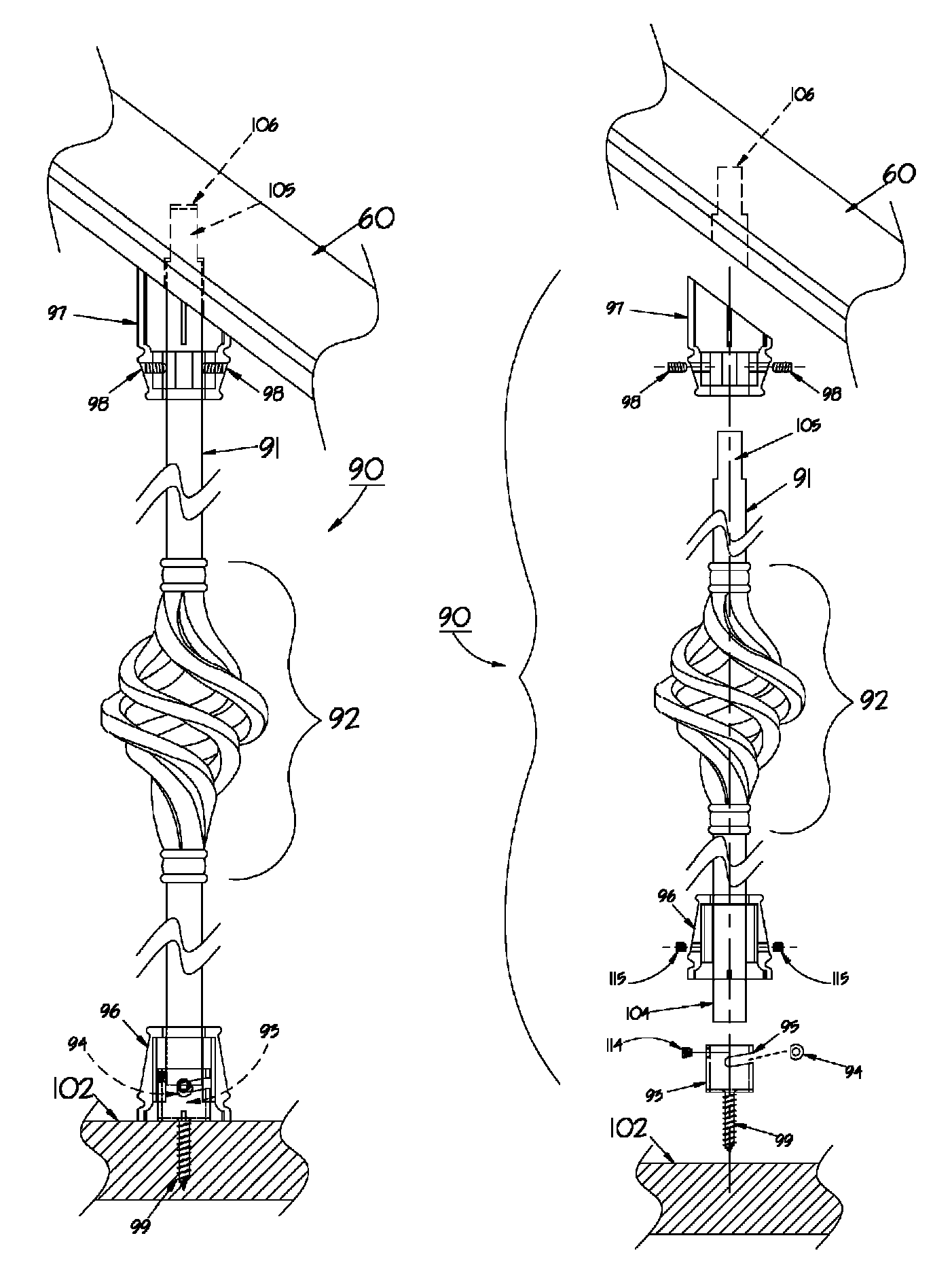
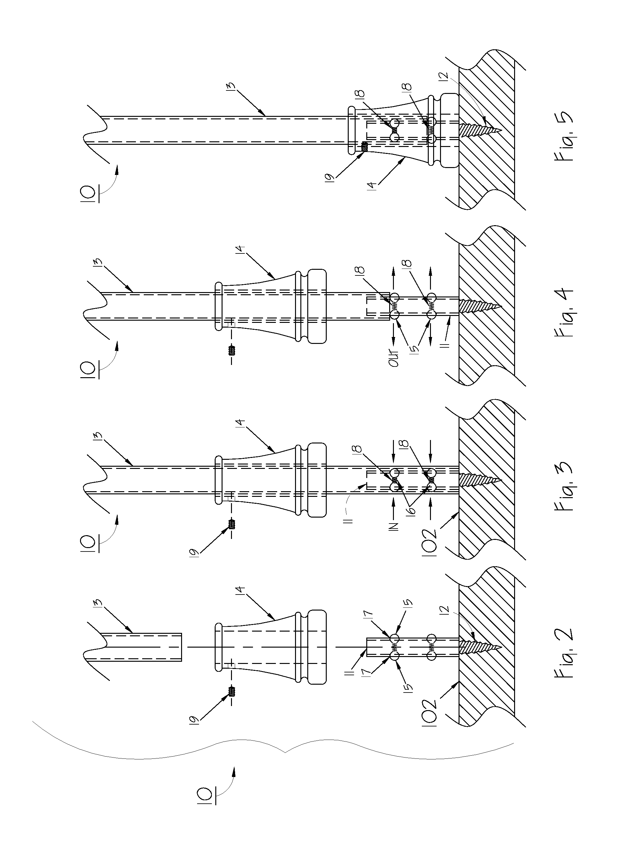
[0014]The present invention prevents the necessity of removing the entire handrail due to the longitudinal adjustability of the balusters which take on one or more of several embodiments with various adjustable means. First, a baluster is described which includes a longitudinal shaft, an extension adjustably connected to the shaft containing a sphere set which is resiliently loaded. Another embodiment includes an extension with an angled slot which utilizes a locking pin while yet another embodiment includes an extension having a plurality of mounting holes for receiving allen screws to provide an adjustable connection to the longitudinal shaft. Another form of the invention utilizes a double threaded hanger bolt for joining a base extension to a baluster shaft. In the method of use, the baluster shaft having a longitudinal channel is placed over the extension and sets of spheres. The shaft can then be raised along the extension and the sphere sets then extend to prevent

Problems solved by technology

Many homes and offices utilize stairway handrails and balusters which sometimes become damaged during activities such as moving furniture, equipment or inadvertent striking of the balusters or the like.
Such balusters which are oftentimes installed with the use of nails, screws, or adhesives are often difficult to remove.
During reinstallation or repair work it is time consuming and usually not desirable to remove the entire handrail.
However, as conventional balusters are often fitted within channels in the handrail, to remove only a single baluster is exceedingly difficult without damaging the handrail or adjacent balusters.
It is labor intensive and expensive to replace conventional balusters, whether replacing one, several or all.

Method used


Image

  • Baluster system and method
  • Baluster system and method
  • Baluster system and method

Examples


Embodiment Construction

is set forth below.

SUMMARY OF THE INVENTION

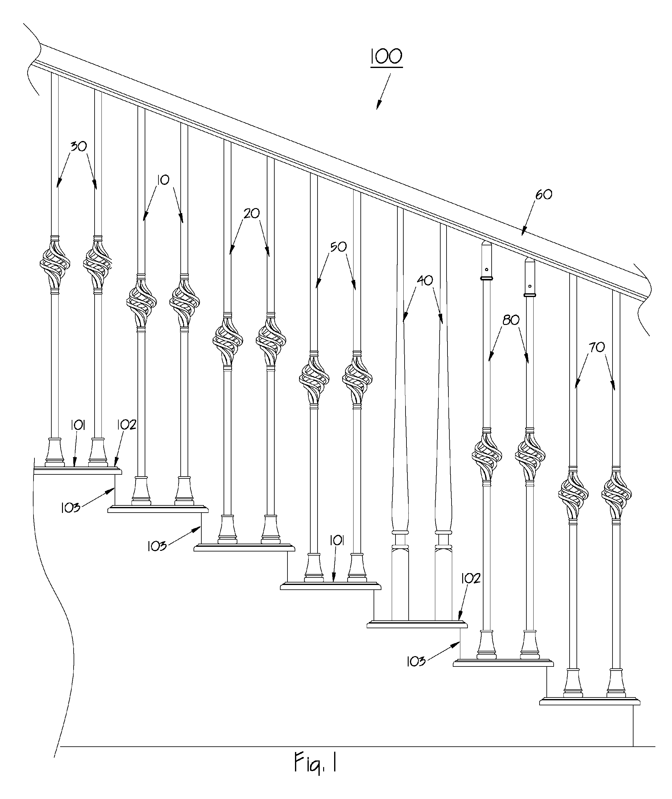
[0012]The aforesaid and other objectives are realized by providing a method for on site exchange or replacement of one or more installed stairway balusters that have been conventionally manufactured by turning on a lathe for a chosen design. Balusters of conventional type have no longitudinal adjustability and are usually formed having an average length and are then cut to a precise height or length on site during the installation process. Stair treads formed of oak or other dense woods are often drilled if required to form a baluster socket. Once the balusters are installed in the tread sockets and optionally the stair well landings, a handrail containing a series of shallow channels for receiving the tops of the balusters can then be attached by the use of a standard fastener such as adhesives, nails or screws. Initial installation is then complete. The baluster components may be formed from wood, metal or plastics as best suited for a pa...


PUM


Abstract

Stairway balusters are described which includes baluster extensions for ease in use, adjustability and convenience during installation, replacement or remodeling. The various extensions illustrated all allow the baluster shaft to adjust longitudinally. If a single baluster is being replaced on site, the baluster can be shortened using the adjustable features while removing. Also, during retrofitting the described method allows a baluster to be shortened, positioned in place and then lengthened to the desired height without undue modification or effort by the installer. Various extension embodiments are demonstrated.

Description

[0001]This is a continuation-in-part of and claims benefits under pending prior patent application Ser. No. 12 / 206,802 filed 9 Sep. 2008 now abandoned.FIELD OF THE INVENTION[0002]The invention herein pertains to stairway balusters and particularly pertains to stairway balusters which can be easily installed, exchanged or replaced during construction, remodeling or redecorating the interior of a building such as a house or office.DESCRIPTION OF THE PRIOR ART AND OBJECTIVES OF THE INVENTION[0003]Many homes and offices utilize stairway handrails and balusters which sometimes become damaged during activities such as moving furniture, equipment or inadvertent striking of the balusters or the like. Such balusters which are oftentimes installed with the use of nails, screws, or adhesives are often difficult to remove. During reinstallation or repair work it is time consuming and usually not desirable to remove the entire handrail. However, as conventional balusters are often fitted within ...

Claims


Application Information

Patent Timeline
IPC IPC(8): E04C3/00
CPCE04F11/1814E04F11/1817E04F11/1846E04F11/025E04F2011/1827E04F2011/1887E04F2011/1889
Inventor LIM, KOK JIT
Owner S V INT
Learn More