Workholding clamping assembly

a technology of workholding and clamping parts, applied in the direction of chucks, mechanical equipment, manufacturing tools, etc., can solve the problems of large volume of conventional workholding clamping parts, and achieve the effect of reducing the force and reducing the for

Inactive Publication Date: 2011-07-05
HARDINGE INC
View PDF62 Cites 18 Cited by
  • Summary
  • Abstract
  • Description
  • Claims
  • Application Information

AI Technical Summary

Benefits of technology

[0009]Another aspect of one or more embodiments of this invention provides a compact pneumatic failsafe workholding clamping assembly.
[0010]Another aspect of one or more embodiments of this invention provides a compact workholding clamping assembly that enables an orientation-specific mounting of a collet thereto.
[0011]Another aspect of one or more embodiments of this invention provides a failsafe workholding clamping assembly that amplifies a closing force provided by a driver in order to reduce the force that the driver must generate to close the collet. The force amplifier may also reduce a force required to overcome the closing force of the driver to open the collet.
[0020]According to a further aspect of one or more of these embodiments, the base includes a spindle having a bore therein that is concentric with the axis. The workholding clamping assembly further includes a collet disposed in the bore. The collet has gripping and released positions. The collet and spindle include mating surfaces that form a non-zero angle with the axis. The collet has a threaded portion that threadingly engages the threaded portion of the draw bar. Axial movement of the draw bar toward its closed position moves the collet toward its gripping position. The collet and spindle include mating surface features that permit the collet to extend into the bore in the spindle in a predetermined rotational position. The mating surface features prevent the collet from rotating relative to the spindle.

Problems solved by technology

Unfortunately, such large drivers make conventional workholding clamping assemblies large, axially long, and radially wide.

Method used


Image

  • Workholding clamping assembly
  • Workholding clamping assembly
  • Workholding clamping assembly

Examples


Embodiment Construction

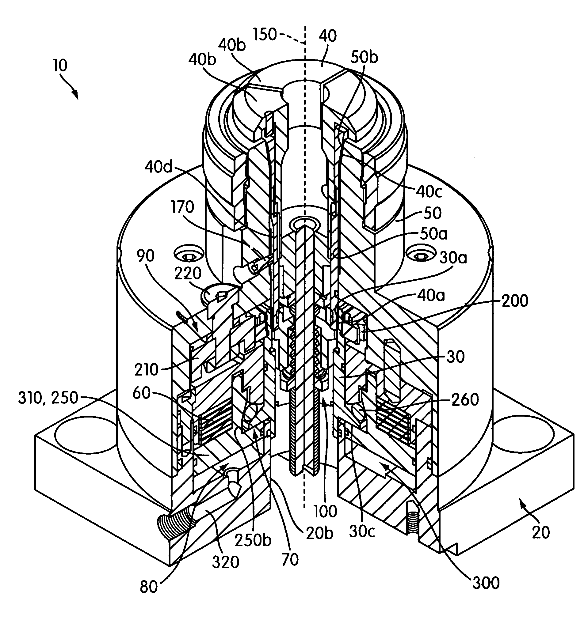
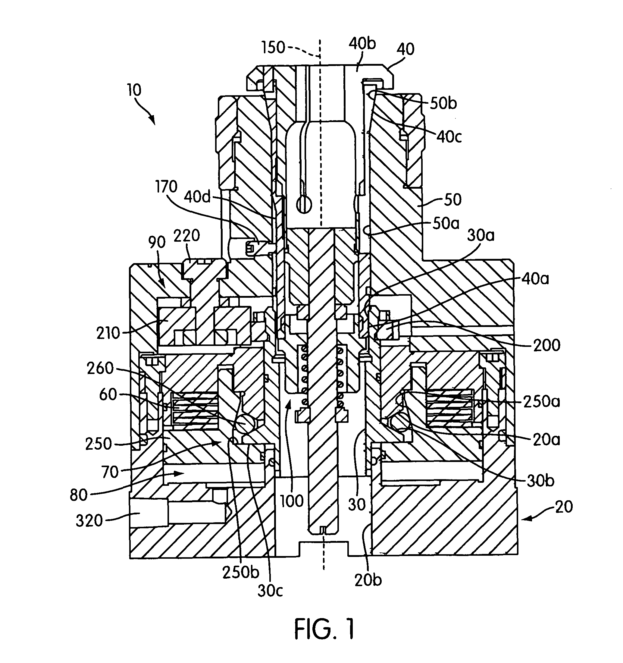
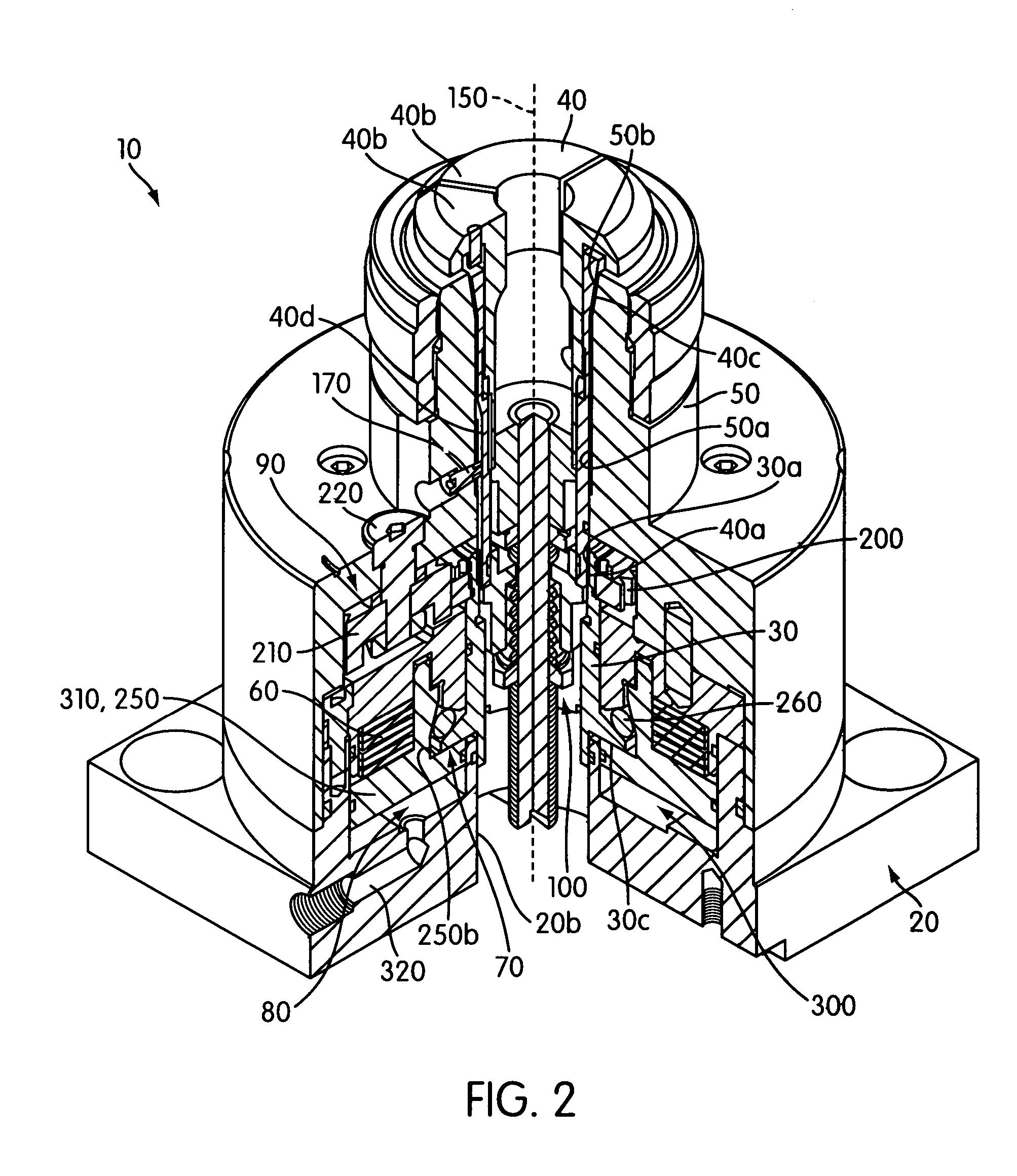
[0031]FIGS. 1-4 illustrate a failsafe workholding clamping assembly 10 for holding a work piece (e.g., a tool, a blank, etc.) according to an embodiment of the present invention. FIGS. 1 and 2 illustrate the workholding clamping assembly 10 in an open / released position, while FIGS. 3 and 4 illustrate the workholding clamping assembly 10 in a closed / gripping position.

[0032]As shown in FIG. 1, the workholding clamping assembly 10 comprises a base 20, a draw bar 30, a collet 40, a spindle 50, a driver 60, a force amplifier 70, a collet opener 80, a draw bar rotating mechanism 90, and a work piece ejector 100. However, one or more of these components may be omitted without deviating from the scope of the present invention.

[0033]As shown in FIG. 2, the base 20 of the workholding clamping assembly 10 includes a forward cylindrical portion and a rearward square mounting portion with mounting holes. However, the base 20 could have any other suitable shape without deviating from the scope of...


PUM


Abstract

A failsafe workholding clamping assembly includes a base, an axially slidable draw bar and collet, and a force amplifier. A driver applies a continuous driving force to the force amplifier. The force amplifier amplifies the driving force and applies a resulting amplified force to the draw bar to bias the draw bar toward its closed position and the collet toward its gripping position. A collet opener mounts to the base and selectively applies an opening force to the draw bar to counteract the driving force and move the collet into its released position. The workholding clamping assembly holds a collet in a predetermined rotational orientation and includes a draw bar rotating mechanism to enable an operator to rotate the draw bar to threadingly engage the draw bar and a rotationally-fixed collet.

Description

CROSS REFERENCE[0001]This application claims priority to U.S. Provisional Patent Application Ser. No. 60 / 714,268, titled “Workholding Clamping Assembly,” filed Sep. 7, 2005, the entire contents of which are hereby incorporated by reference.BACKGROUND OF THE INVENTION[0002]1. Field of the Invention[0003]The present invention relates to failsafe workholding clamping assemblies for holding work pieces.[0004]2. Description of Related Art[0005]As shown in JP2002046005, it is known to provide a failsafe workholding clamping assembly that maintains a collet in a closed position unless an opening force is applied. Failsafe workholding clamping assemblies are advantageous because they will not accidentally release a work piece, even if power to the closing mechanism is lost (e.g., loss of drawbar force, pneumatic force, hydraulic force, etc.).[0006]Conventional failsafe workholding clamping assemblies include drivers (e.g., compression springs) that close the collets in the absence of a coun...

Claims


Application Information

Patent Timeline
Patent Type & Authority Patents(United States)
IPC IPC(8): B23B31/20
CPCB23Q1/0072Y10T279/1033Y10T279/1258Y10T279/3481Y10T279/17547Y10T279/17341Y10T279/1012
Inventor SOROKA, DANIEL PKESTERKE, III, RICHARD
Owner HARDINGE INC
Why Eureka
Try Eureka