Infant stroller rocking device

a technology for strollers and strollers, which is applied in the direction of children's furniture, carriage/perambulator accessories, sofas, etc., can solve the problems of destabilising the stroller, affecting the stability of the stroller, and affecting the safety of the stroller

Inactive Publication Date: 2011-07-05
SANDERS ASSOCIATES +1
View PDF22 Cites 18 Cited by
  • Summary
  • Abstract
  • Description
  • Claims
  • Application Information

AI Technical Summary

Benefits of technology

[0018]By providing an arrangement where the only substantial movement of the buggy is through wheels that are supported on platforms which are themselves supported on linear bearings, the friction that has to be overcome is minimised. For example, a typical three-wheeled off-road buggy weighs 10.5 kg. A large three-year-old child weighs 18.6 kg (90th percentile boy, USA). With the child in the buggy, the force needed to lift a wheel is 58 N (front,×1) or 114 N (rear×2). The force required to pull the buggy forward on carpet is about 23 N. The force required to push the buggy sideways at the rear, however, when it is supported on linear rolling bearing units is only about 2.5 N (and half that if only the front wheel is moved sideways). Consequently, both the motor and battery power required are small, making such a unit easily portable.
[0020]Although not essential, said first or second wheel may the wheel or wheels of the carrier that are provided with a brake and said method may then further comprise the step of applying said brakes when disposing said wheels on the first and second units. This may have the disadvantage of causing unnecessary stresses on the device or buggy if the movements resulting from the operation of the motor would otherwise cause rolling of the braked wheels on the platforms. This can be minimised by aligning the drive unit, and the slave unit where used, with the direction of oscillation of the buggy.
[0025]In any event, the backwards and forwards motion on the platform is slight, and only sufficient to accommodate the sideways motion (preferably about 50 mm in amplitude) of that end of the carrier supported on the unit(s). Indeed, a certain amount of to and fro movement is inevitably required of the wheels on the platforms. Preferably the platforms are flat in a direction transverse said first direction and have upstanding walls spaced apart and parallel said first direction to retain a wheel on the carrier from rolling off the platform. Preferably, ridges are disposed on the top surface of the platform transverse said first direction to improve friction between the wheel and platform in said first direction.
[0027]Preferably, the platform of said drive unit incorporates a housing at one end of the platform, said housing receiving the motor. Preferably, the motor is arranged with its rotational axis perpendicular to the platform and includes a crank having a pinion received in a slot in the base so that, as the crank is rotated by the motor, the platform is oscillated back and forth over said base. Preferably a gearbox is interposed between said crank and motor to reduce the speed of rotation of the crank relative to the motor.
[0032]Preferably, the base has a base cover connected thereto and spaced therefrom and provided with an aperture having an upstanding lip, which aperture is sized to fit said ball cage within its range of movement. Preferably, said platform has a depending lip spaced closely from said base cover, which cover is sized to exceed the size of the platform throughout its entire range of movement relative to the base. The upstanding lip of the base cover, in association with the covering thereof by the platform with its depending lip, ensures that there is only a labyrinthine path for dust and dirt to find its way to the bearings. The upstanding lip should also prevent liquid spillages (such as infant drinks) from getting to the bearings.
[0033]Indeed, the platform being smaller than the base means that, as the platform moves over the base there is a constant, unchanging clearance between them. This avoids the possibility of any finger-trapping by inquisitive children.

Problems solved by technology

There are various problems with all these arrangements, some of which are that the stroller or pram may be lifted a significant step up off the ground.
Alternatively, if only one end of the pram is lifted, there is an increased risk of the pram tipping over.
Consequently, substantial lifting by a rocking device may destabilise a stroller.
Another problem is that the rocking device frequently needs to “fit” the buggy or pram in question.
Nowadays there are such a plethora of different shapes and sizes of buggy and stroller that no single device presently available is suitable for them all, at least, not if it is portable or does not have complicated adjustments.
Any buggy can be rocked by such a device, but the device is consequently not portable.
Likewise, some arrangements provide for adjustments whereby different configurations may be catered for (eg WO2004 / 062977), but these arrangements are complicated.
Yet, many of the devices presently available are far from portable, and some even challenge transportability.
Furthermore, a potential problem with portable arrangements is that babies and their buggies are a significant weight and the energy required to move them, particularly with up and down movements, can be substantial, making batteries having a useful lifetime, (and which are needed for driving the unit when away from home), very heavy.
Indeed, the situation is often that, because the friction is so high, instead of oscillating the pram or buggy backwards and forwards, the rocking device simply oscillates itself backwards and forwards, using the buggy as an anchor.
Another issue is that, where the stroller or pram is rocked backwards and forwards on its own wheels, and this means that absolute confidence must be had in the system that the buggy will not roll off its support and roll away by itself.

Method used


Image

  • Infant stroller rocking device
  • Infant stroller rocking device
  • Infant stroller rocking device

Examples


Embodiment Construction

[0047]For the avoidance of doubt, the terms “buggy”, “stroller”, “pram” etc are used herein interchangeably and refer to any wheeled infant carrier, including a cot or bed provided with wheels.

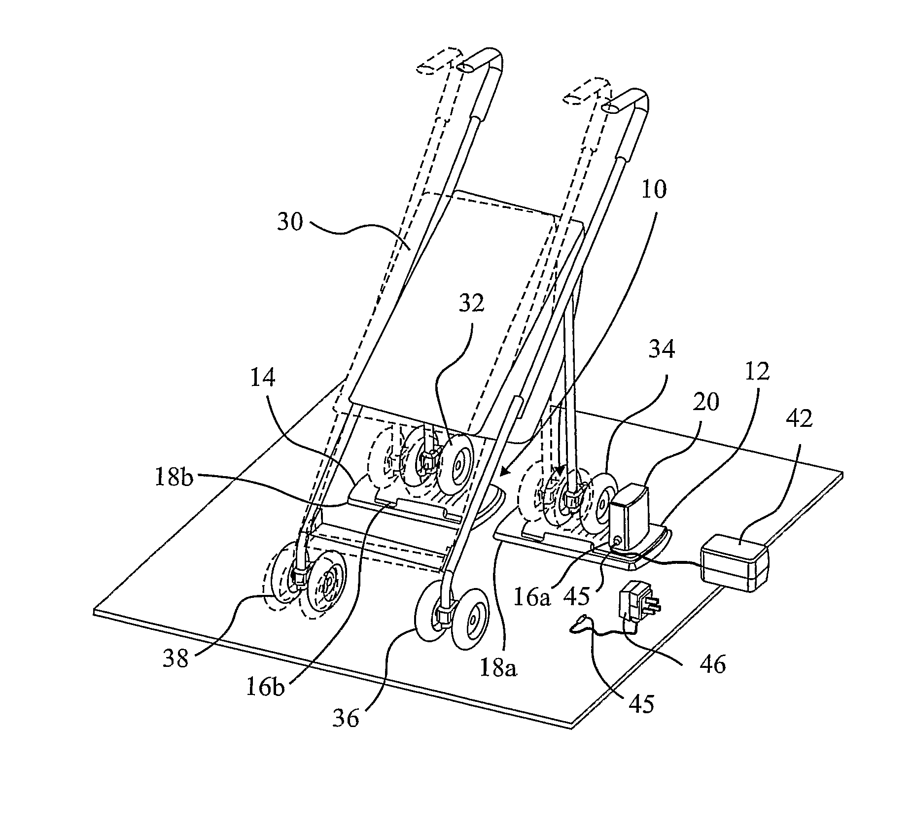
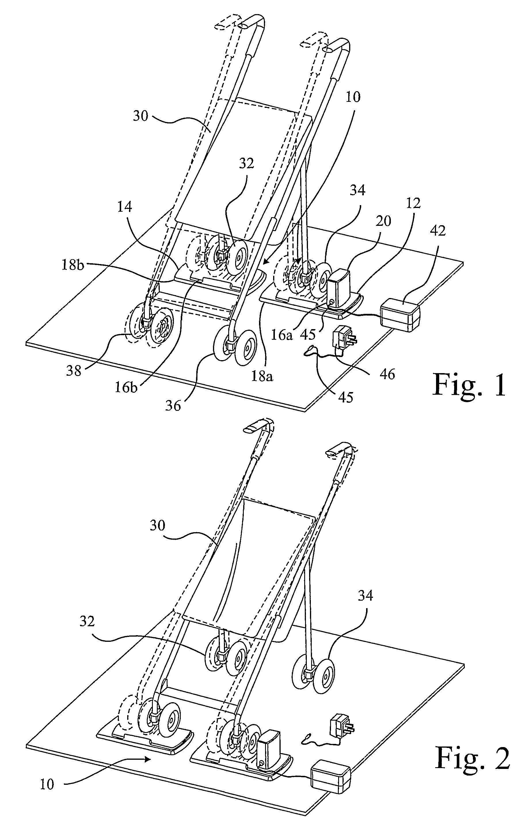
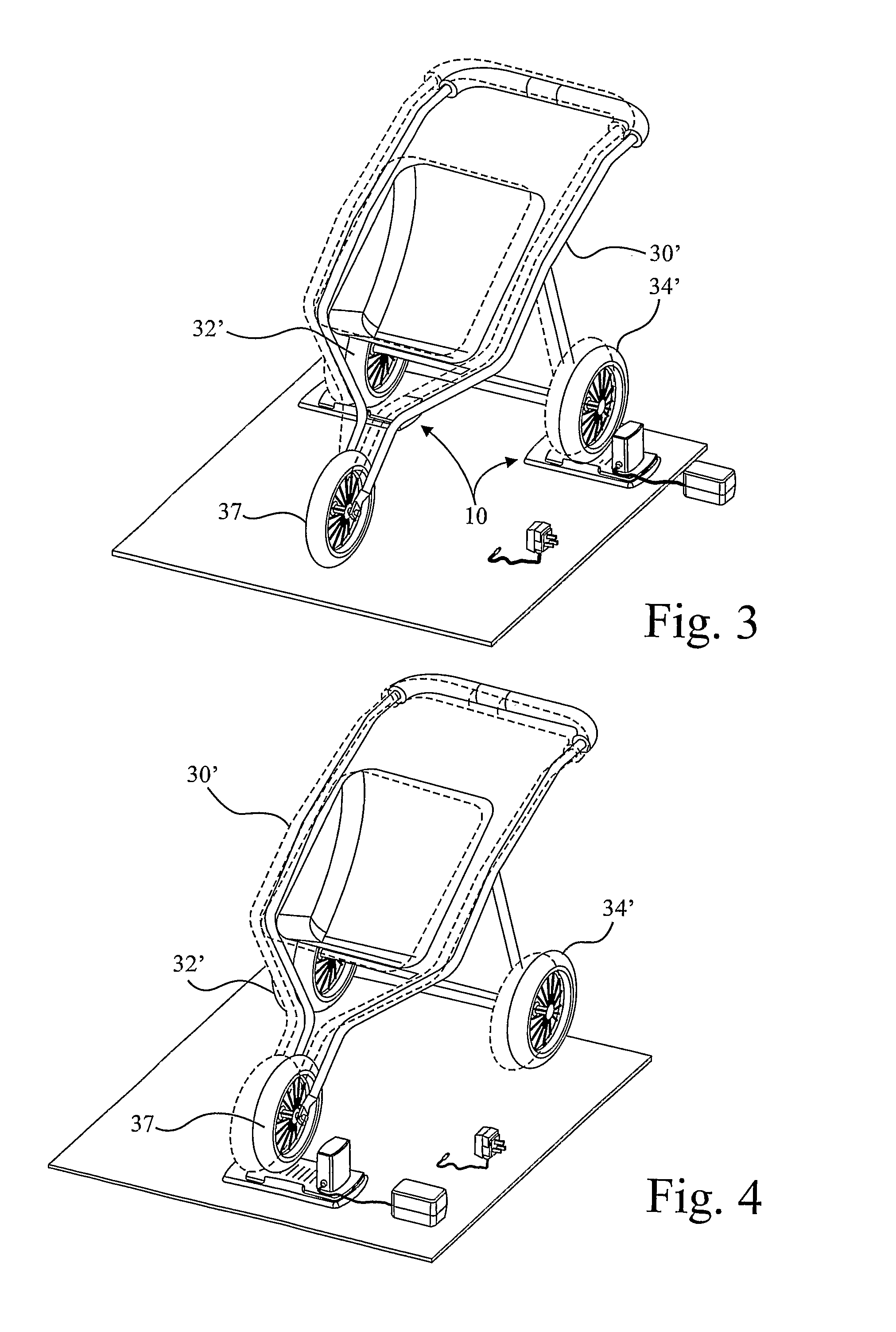
[0048]FIGS. 1 to 6 show a rocking device 10 in accordance with the present invention. The device 10 comprises a drive unit 12 and a slave unit 14. Both have similar constructions comprising a platform 16a,b and a base 18a,b. As explained further below, each platform is arranged to be freely translatable back and forth over the respective base. In the case of the slave unit 14, the platform 16b is simply free to move back and forth over the base 18b. However, with the drive unit 12, the platform 16a is provided with a housing 20 for a motor which is arranged to drive the platform 16a back and forth over the base 18a.

[0049]In FIGS. 1 and 2, a four wheeled buggy 30 is shown, with its rear wheels 32,34 supported respectively on the platforms 16b,a of the slave unit 14 and drive unit 12. When the ...


PUM


Abstract

A method of rocking a wheeled infant carrier (30) comprises using a rocking device (10) having a pair of discrete units (12,14). Each unit has a ground-engaging base (18a,b) and a platform (16a,b) supported thereon through bearings for movement relative to the base in a first direction. A drive one (12) of the units has a motor in a housing (20) arranged to drive the platform (16a) of the drive unit relative to its base back and forth in said first direction. A first wheel (34) of the carrier (30) is placed on the drive unit and a second wheel (32) on the second, slave unit (14), with the axes of rotation of the wheels being arranged parallel said first direction. The motor is operated to rock that end of the carrier that is supported by those wheels from side to side.

Description

[0001]This invention relates to a rocking device for infant strollers, prams buggies and other wheeled cots and the like and in which a baby or infant is carried and it is desired to rock the child to facilitate quiet sleep.BACKGROUND[0002]There are numerous patents disclosing various arrangements of this kind. GB-A-2219199 discloses a moveable frame oscillated back and forth over a smaller, stationary frame by a motor mounted on the stationary frame. A crib or infant carriage is placed on the moveable frame. WO-A-95 / 23722 discloses a frame supported off the ground on which a pram can be disposed and a mechanism is provided to rock the frame in different ways. EP-B-415736 discloses an arrangement having two receptacles for the front or back wheels of a pram, and these are rocked backwards and forwards.[0003]GB-A-2231005 provides a housing supported on the ground and a single wheel holder for a stroller, which stroller is pulled backwards and forwards by a motor in the housing recipr...

Claims


Application Information

Patent Timeline
Patent Type & Authority Patents(United States)
IPC IPC(8): B62B9/22
CPCB62B9/22A47D9/02
Inventor SANDERS, ANTHONY JONATHANHANCOCK, GAVIN
Owner SANDERS ASSOCIATES
Why Eureka
Try Eureka