
Projector having cooling device for cooling target object and control device for controlling cooling device

a technology of target objects and cooling devices, which is applied in the field of projectors, can solve the problems of not being able to directly attach the temperature sensor to the optical component for performing measurement, the temperature control performed based on the external room temperature and the internal temperature is not necessarily appropriate, and the overheating of the target object such as the optical component inside the projector cannot necessarily be estimated correctly, so as to prevent the overheating of the target object, maintain the stable operation of the projector, and prevent the overh

Inactive Publication Date: 2011-07-05
SEIKO EPSON CORP
View PDF14 Cites 2 Cited by
  • Summary
  • Abstract
  • Description
  • Claims
  • Application Information

AI Technical Summary

Benefits of technology

[0010]Therefore, an advantage of the invention is to provide a projector capable of appropriately performing the cooling control based even on the detected temperature measured indirectly without directly measuring the temperature of the target object, thereby preventing the target object from overheating.
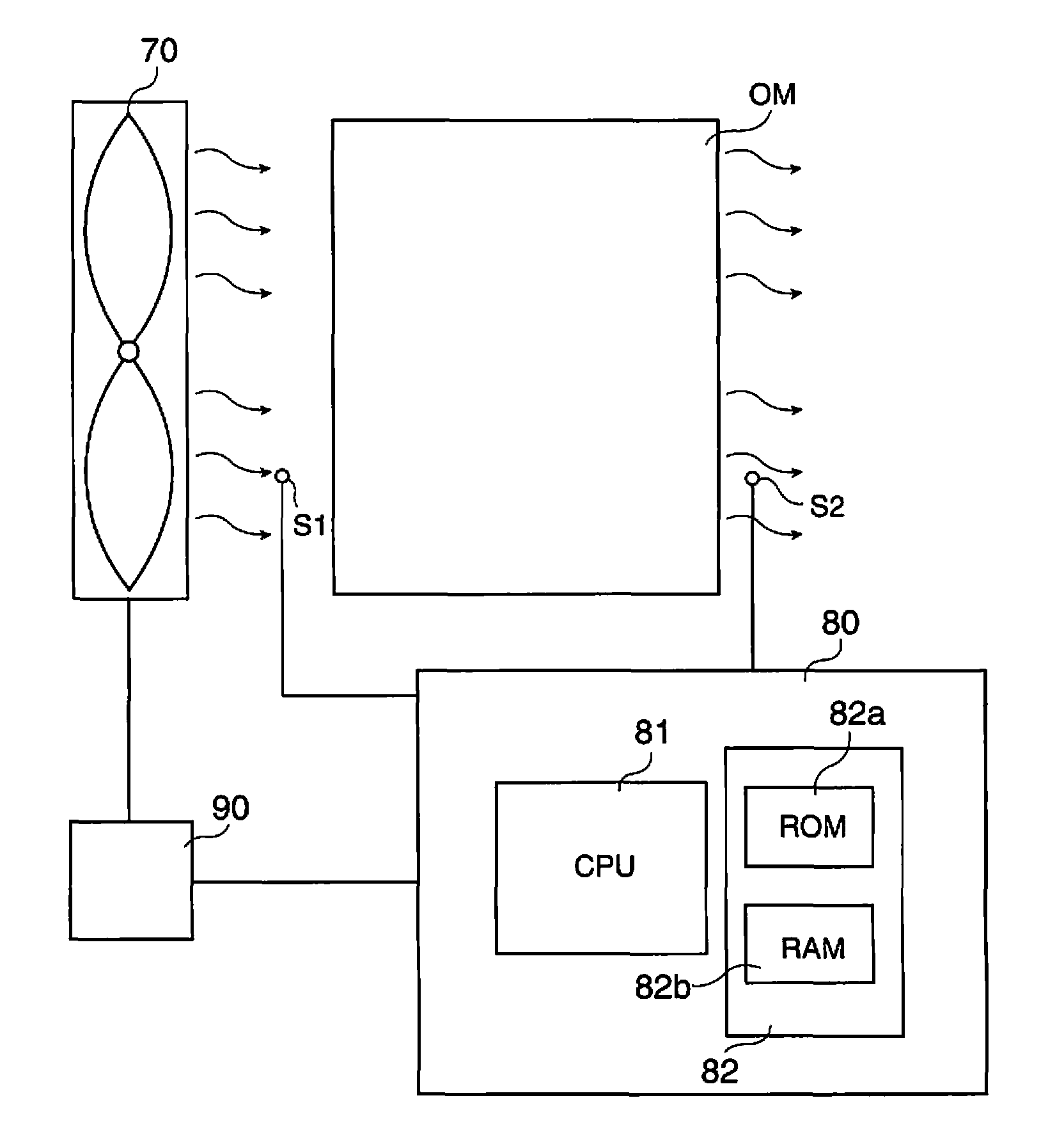
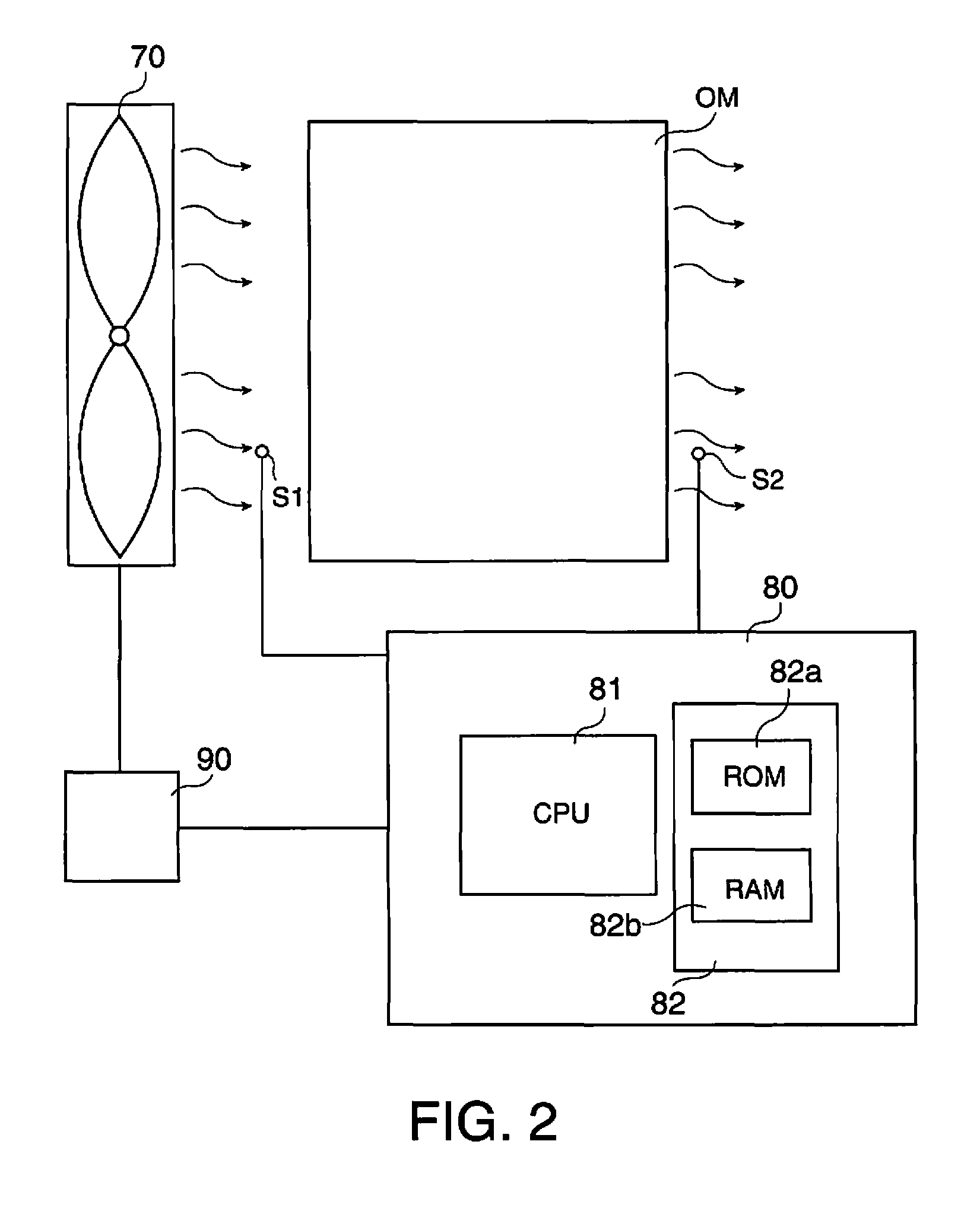
[0011]A projector according to an aspect of the invention includes (a) a cooling device for performing cooling of a target object housed inside a housing, (b) a first temperature sensor disposed in an anterior stage of the target object on a cooling path formed by the cooling device inside the housing, and for measuring a first detection temperature in an anterior area of the cooling among peripheral areas of the target object, (c) a second temperature sensor disposed in a posterior stage of the target object on the cooling path, and for measuring a second detection temperature in a posterior area of the cooling among the peripheral areas of the target object, and (d) a control device for performing calculation regarding the temperature of the target object from the first detection temperature and the second detection temperature, and controlling the cooling device based on the result of the calculation.
[0012]According to the projector described above, by measuring the temperatures in the anterior side of the cooling and the posterior side of the cooling in the periphery of the target object by the first temperature sensor and the second temperature sensor, and performing the calculation regarding the temperature of the target object from the detection temperatures thus measured, the information regarding the temperature of the target object can be calculated with relative accuracy even with the estimated temperatures measured indirectly. Further, since the cooling device can appropriately be controlled in accordance with the calculated result, as a result, it becomes possible not only to perform the temperature management of the target object, but also to prevent the target object from overheating.
[0013]Further, according to a specific aspect of the invention, the control device performs setting of intensity of the cooling performed by the cooling device based on the result of the calculation. In this case, the setting of intensity of the cooling corresponding to the estimated temperature of the target object becomes possible.
[0014]Further, according to another specific aspect of the invention, the control device changes setting of the cooling performed by the cooling device in accordance with an update of the result of the calculation, thereby controlling a temperature variation of the target object within a certain range. In this case, since the setting of the cooling of the cooling device can be changed in accordance with the variation of the temperature of the target object by feeding-back the condition of the temperature of the target object, it becomes possible to control the temperature variation of the target object within a certain range, thus maintaining the stable operation of the projector.
[0015]Further, according to another specific aspect of the invention, the control device performs the calculation regarding the temperature of the target object using a predetermined conversion formula including a term having the first detection temperature and a term having a square root of a temperature difference obtained by subtracting the first detection temperature from the second detection temperature. In this case, as the predetermined conversion formula, the following formula can be cited.Tp=Tr+a√{square root over (Ti−Tr)}+b

Problems solved by technology

However, in using the projector, for example, regarding an extent of overheating of the optical component inside the projector, the extent of overheating of the target object such as an optical component inside the projector such as a rate of increase in the temperature thereof cannot necessarily be estimated correctly only by the internal temperature of the projector device because of an influence of, for example, clogging of an air filter for taking the external air in the projector.
In other words, the temperature control performed based on the external room temperature and the internal temperature is not necessarily appropriate.
Therefore, it is not necessarily easy to directly attach the temperature sensor to the optical component for performing measurement because it is required to dispose the temperature sensor at a place where the temperature sensor does not make a shadow on the optical path.
Further, there is a possibility of damaging the temperature sensor because of the influence of the heat from the optical component depending on the place where the temperature sensor is attached.

Method used


Image

  • Projector having cooling device for cooling target object and control device for controlling cooling device
  • Projector having cooling device for cooling target object and control device for controlling cooling device
  • Projector having cooling device for cooling target object and control device for controlling cooling device

Examples


Embodiment Construction

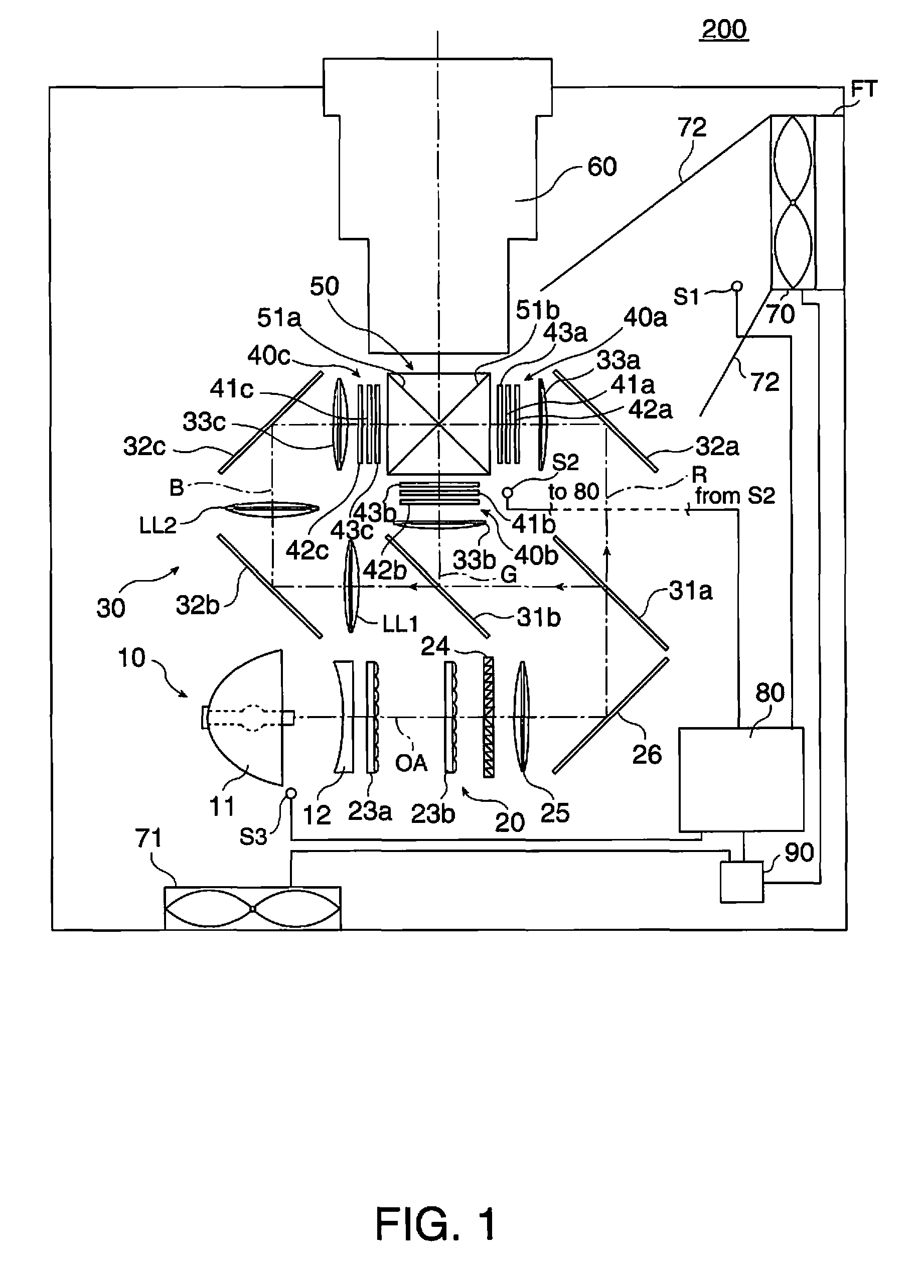
[0027]FIG. 1 is a conceptual diagram for explaining a structure of a projector according to a first embodiment. The projector 200 of the present embodiment is provided with a light source device 10, an equalizing optical system 20, a color separation optical system 30, liquid crystal light valves 40a, 40b, 40c, a cross dichroic prism 50, a projection lens 60, an air intake fan 70 for introducing external air in the inside of the projector 200 to perform cooling in an air-cooling manner, an exhaust fan 71 for discharging the air used for cooling to the outside, a drive device 90 for driving the fans 70, 71, and a control device 80 for controlling the operations of the drive device 90 and so on. Here, the light source device 10 and the equalizing optical system 20 forms an illumination light source device. It should be noted that these optical components and so on forming the projector 200 are integrally housed by a housing SC.

[0028]In the projector 200, the light source device 10 is ...


PUM


Abstract

A projector includes a cooling device for performing cooling of a target object housed inside a housing, a first temperature sensor disposed in an anterior stage of the target object on a cooling path formed by the cooling device inside the housing, and for measuring a first detection temperature in an anterior area of the cooling among peripheral areas of the target object, a second temperature sensor disposed in a posterior stage of the target object on the cooling path, and for measuring a second detection temperature in a posterior area of the cooling among the peripheral areas, and a control device for performing calculation regarding the temperature of the target object from the first detection temperature and the second detection temperature, and controlling the cooling device based on the result of the calculation.

Description

BACKGROUND[0001]1. Technical Field[0002]The present invention relates to a projector having a cooling device incorporated therein and capable of cooling a target object such as an optical component on demand.[0003]2. Related Art[0004]There is known a device in, for example, a light path deflection device or a projector having an optical component such as a light path deflection element using a liquid crystal material, having internal temperature sensors for measuring the temperature of the sections the temperature of which the tendency of the temperature of the component can be figured from, and performing control of an air blower for sending air to the optical component in accordance with the temperature measured by each of the temperature sensors in order for maintaining the temperature of the optical component fixedly.[0005]Further, there is known a device having an external temperature sensor for detecting the temperature of the air distributed to the optical component and an in...

Claims


Application Information

Patent Timeline
Patent Type & Authority Patents(United States)
IPC IPC(8): G03B21/16
CPCG03B21/16
Inventor KATO, HISAMARO
Owner SEIKO EPSON CORP
Learn More