Filtration apparatus

a filtration apparatus and filtration tube technology, applied in sedimentation settling tanks, membranes, separation processes, etc., can solve the problems of insufficient air diffusion between membranes, large volume of membrane installation parts, and difficult installation of membranes at a high density, so as to achieve stable filtration function, efficiently and reliably remove suspended components, and vibrate membrane surfaces.

Active Publication Date: 2011-07-05
SUMITOMO ELECTRIC IND LTD
View PDF21 Cites 4 Cited by
  • Summary
  • Abstract
  • Description
  • Claims
  • Application Information

AI Technical Summary

Benefits of technology

[0088]As described above, according to the filtration apparatus of the present invention, the other ends of a plurality of the hollow fiber membranes disposed at the side of the pressurized gas jetting means are supported by the holding member with the gaps formed between the other ends of the hollow fiber membranes and the holding member. Therefore the holding member supports the hollow fiber membranes and at the same time allows the gas passing through the gaps between the hollow fiber membranes and the holding member to be imparted to the membrane surfaces of the hollow fiber membranes. Thus it is possible to reliably vibrate the membrane surfaces and efficiently and reliably remove the suspended component which has deposited on the membrane surfaces or in the gaps between the membranes by the peel-off owing to the liquid flowing along the surfaces of the hollow fiber membranes. Further because it is possible to apply bubbles sufficiently to the entire hollow fiber membrane module in which the hollow fiber membranes are collectively set, it is possible to prevent the solid content from depositing on the lower portion of the hollow fiber membrane module and secure a stable filtration function.
[0089]Further by holding the bent portions of the hollow fiber membranes by the holding member with the gaps formed between the bent portions of the hollow fiber membranes and the holding member, bubbles are sufficiently applied to the lowermost portion of each of the hollow fiber membranes. Thus it is possible to prevent the deposition of the solid content. Therefore the effective area of the membrane little decreases and thus the filtration function hardly deteriorates. Thereby water can be treated in a stable amount. Further by folding the hollow fiber membrane double, it is possible to secure a larger membrane surface area than a type of the hollow fiber membrane, both ends of which are closed. Therefore the filtration apparatus is capable of treating a large amount of water.

Problems solved by technology

To diffuse the air sufficiently, it is necessary to space the adjacent sheet-shaped flat hollow fiber membrane modules 101 to some extent, and hence it is difficult to install membranes at a high density.
Therefore the membrane-installing part has a large volume.
The filtration method has a problem that when air is diffused entirely from below the membrane module 101, only the surfaces of the hollow fiber membranes 103 are air-diffused, and insufficient air diffusion occurs between membranes and particularly in the neighborhood of the water-collecting portion where the membranes are liable to be clogged.
The filtration method has another problem that the hollow fiber membranes are liable to be broken because the amplitude of the membranes is large in the vicinity of the water-collecting portion, namely, in the vicinity of the hollow fiber membranes-bonded portions, and a load is applied thereto.
Thus the hollow fiber membranes are liable to be broken in the vicinity of the bonded portions thereof.
Thus the filter has a problem that an insufficient air diffusion is performed between the membranes.
But a plurality of the gas-jetting holes generates a larger amount of air than a necessary amount, which costs an extra running cost.

Method used


Image

  • Filtration apparatus
  • Filtration apparatus
  • Filtration apparatus

Examples


example 1

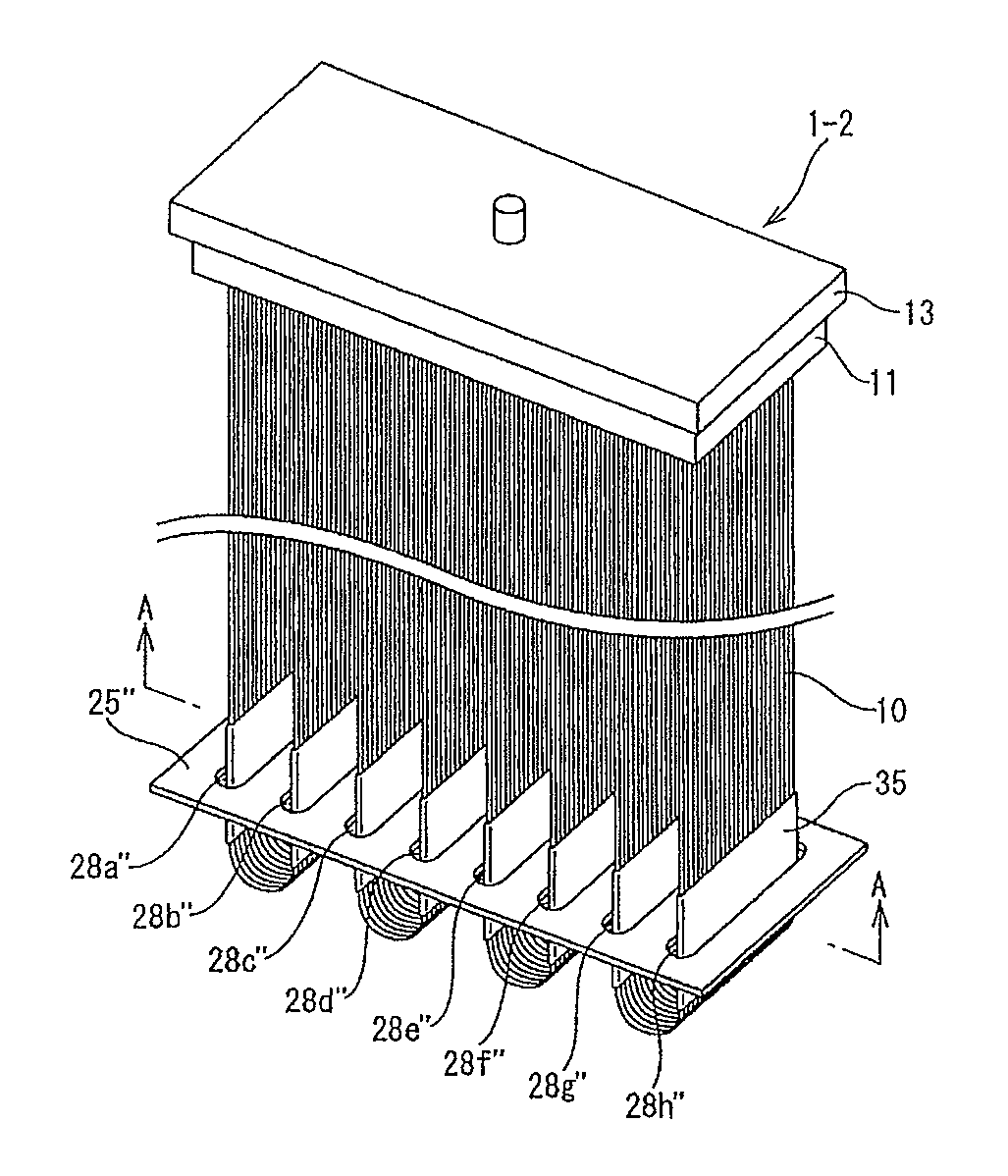
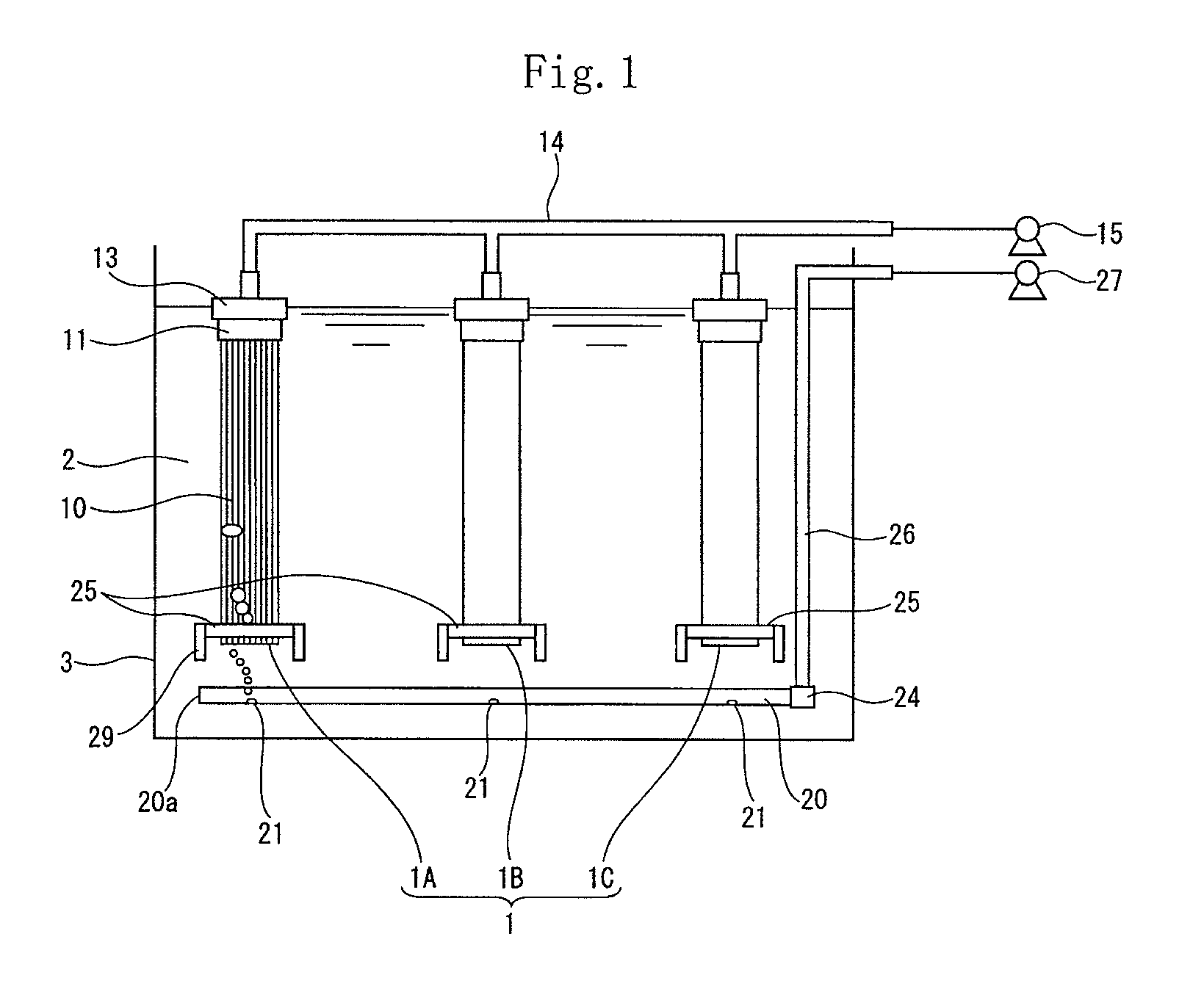
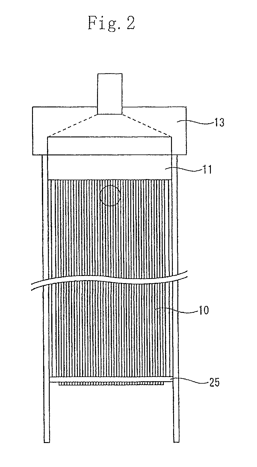
[0217]As the hollow fiber membrane 10, drawn hollow fiber membrane made of PTFE having an inner diameter of 1 mm, an outer diameter of 2 mm, a porosity of 75%, a pore diameter of 0.45 μm, and an effective length of 1500 mm is used. One hollow fiber membrane module 1 has 945 hollow fiber membranes. As shown in FIG. 21(B), as the holding member 25, a plate, made of PVC resin, having a dimension of 150 mm×150 mm (length×breadth) through which 945 through-holes having an outer diameter of 3 mm were formed and having a thickness of 5 mm was used.

[0218]Both ends of one double folded hollow fiber membrane were inserted through a pair of the adjacent through-holes with the hollow fiber membrane forming a U shape at the central position thereof.

[0219]After both ends of the U-shaped hollow fiber membranes were inserted into a water-collecting header 13 made of ABS resin having a groove formed therein, with both ends thereof bundled and arranged squarely, both ends thereof were fixed with resi...

example 2

[0223]As shown in FIGS. 22(A), 22(B), and 22(C), the hollow fiber membrane 10 was used similarly to the example 1. Instead of the holding member 25 of the example 1, the sectionally rectangular rod for folding use 70 made of ABS resin was used. By using the rod 70, the hollow fiber membrane 10 was bent so that it was U-shaped. After both ends of the U-shaped hollow fiber membranes were inserted into the water-collecting header 13 made of ABS resin having a groove formed therein, with both ends thereof bundled and arranged squarely, both ends thereof were fixed with resin (urethane resin) for fixing use with both ends thereof kept open to form the fixing member 11 of the hollow fiber membrane module. Thereby the module was formed. The number of the hollow fiber membranes was set to 945, similarly to the example 1. Sucking filtration was performed by setting other conditions similarly to those of the example 1.


PUM

PropertyMeasurementUnit
pressureaaaaaaaaaa
pressureaaaaaaaaaa
diameteraaaaaaaaaa

Abstract

A filtration apparatus for performing solid-liquid separation by immersing a plurality of hollow fiber membranes in a to-be-treated liquid containing a suspended component includes the hollow fiber membranes folded double, a treated liquid collection means communicated with an open end of each of the hollow fiber membranes, a holding member for holding a bent portion of each of the hollow fiber membranes with a gap formed between the bent portion and the holding member, and a gas-jetting means for jetting a cleaning gas from the bent side of each of the hollow fiber membranes to a side of the open end. A gap for flowing the gas jetted by the gas-jetting means is formed between the hollow fiber membranes and the holding member or / and in at least one part of gaps between the hollow fiber membranes.

Description

TECHNICAL FIELD[0001]The present invention relates to a sucking filtration apparatus of an immersion type or a filtration apparatus of an external pressure type for performing solid-liquid separation by immersing a large number of hollow fiber membranes arranged side by side in a to-be-treated liquid containing a suspended component so that treated liquid permeates the hollow fiber membranes, and more particularly to a filtration apparatus including cleaning means having a simple construction for removing the suspended component which has attached to the hollow fiber membranes.BACKGROUND ART[0002]A membrane module in which a plurality of hollow fiber membranes is disposed collectively and circularly and one end or both ends of the hollow fiber membranes is fixed by a fixing member with the one end or both ends of the hollow fiber membranes open to form a water collection portion is mounted and used for the sucking filtration apparatus of the immersion type or the filtration apparatu...

Claims


Application Information

Patent Timeline
Patent Type & Authority Patents(United States)
IPC IPC(8): B01D63/00C02F1/44
CPCB01D61/18B01D63/024B01D63/043B01D65/02C02F1/444B01D2313/06C02F2103/20B01D2313/26B01D2315/06B01D2321/185C02F3/1273B01D2313/21Y02W10/10B01D63/02C02F1/44B01D71/36B01D63/0241
Inventor MORITA, TOORUKAWABE, SHINSUKE
Owner SUMITOMO ELECTRIC IND LTD
Why Eureka
Try Eureka