Voltage controlled oscillators and phase-frequency locked loop circuit using the same

a voltage control and phase-frequency locked loop technology, applied in pulse automatic control, pulse technique, angle demodulation, etc., can solve the problems of increased kvco, increased consumption current, undesired

Active Publication Date: 2011-07-05
MEDIATEK INC
View PDF6 Cites 1 Cited by
  • Summary
  • Abstract
  • Description
  • Claims
  • Application Information

AI Technical Summary

Benefits of technology

[0008]Thus, for high-speed devices, a voltage control ring oscillator with a high center frequency and a small gain (Kvco) is desirable.

Problems solved by technology

However, the consumption current is increased, and Kvco also increases, undesirably.

Method used


Image

  • Voltage controlled oscillators and phase-frequency locked loop circuit using the same
  • Voltage controlled oscillators and phase-frequency locked loop circuit using the same
  • Voltage controlled oscillators and phase-frequency locked loop circuit using the same

Examples


Embodiment Construction

[0027]The following description is of the best-contemplated mode of carrying out the invention. This description is made for the purpose of illustrating the general principles of the invention and should not be taken in a limiting sense. The scope of the invention is best determined by reference to the appended claims.

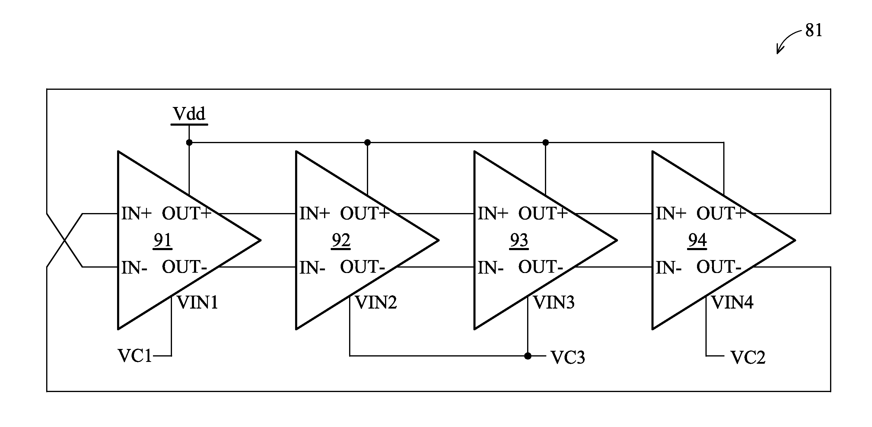
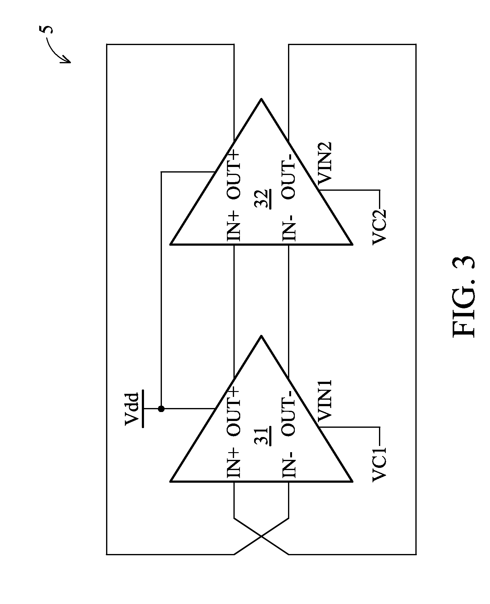
[0028]Voltage controlled oscillators are provided. In an exemplary embodiment of a voltage controlled oscillator in FIG. 3, a voltage controlled oscillator comprises n differential delay cells, that is the voltage controlled oscillator is an n-stage voltage controlled oscillator, wherein n≧2. In the embodiment of FIG. 3, a 2-stage voltage controlled oscillator 3 is given as an example and comprises differential delay cells 31 and 32. The differential delay cells 31 and 32 are serially coupled in a loop. In FIG. 3, one ring connection of the differential delay cells 31 and 32 is given as an example. Referring to FIG. 3, positive and negative output terminals (OUT+ and O...


PUM


Abstract

A voltage controlled oscillator comprising first and second differential delay cells. The first differential delay cell has a first control voltage input terminal. The second differential delay cell is coupled to the first differential delay cell in a loop and has a second control voltage input terminal. The second voltage input terminal is disconnected from the first voltage control input terminal. The first voltage control input terminal receives a first voltage signal, and the second voltage control input terminal receives a second voltage signal different from the first voltage signal.

Description

BACKGROUND OF THE INVENTION[0001]1. Field of the Invention[0002]The invention relates to a voltage controlled oscillator, and more particularly to a voltage controlled oscillator and voltage controlled oscillator applied in a phase-frequency locked loop circuit.[0003]2. Description of the Related Art[0004]A conventional voltage control ring oscillator is formed by n-stages delay cells coupled serially in a ring loop. All the delay cells are controlled by the same adjustable control voltage through their voltage control input terminals, and the oscillation frequency of the voltage controlled ring oscillator is thus obtained. FIG. 1 shows a voltage-to-frequency transfer curve of a conventional voltage control ring oscillator. The slope of the voltage-to-frequency transfer curve is calculated to serve as the gain of the voltage control ring oscillator, as the equation E1:Kvco=dF / dVC  (E1)[0005]wherein Kvco represents the gain of the voltage control ring oscillator, dVC represents a con...

Claims


Application Information

Patent Timeline
Patent Type & Authority Patents(United States)
IPC IPC(8): H03L7/06
CPCH03K3/0322H03L7/087H03L7/0995H03L2207/06
Inventor CHIU, PAO-CHENG
Owner MEDIATEK INC
Why Eureka
Try Eureka