Pre-amplifier for magnetic resonance imaging radio-frequency coil

a radio frequency coil and preamplifier technology, applied in the direction of rf amplifiers, high-frequency amplifiers, instruments, etc., can solve the problem that the operation frequency point of the preamplifier for the magnetic resonance imaging radio-frequency coil is extremely prone to oscillation, and achieve the effect of small gain and significant reduction of the probability of oscillation of the pre-amplifier for the magnetic resonance imaging radio-frequency coil

Active Publication Date: 2019-07-02
SHANGHAI CHENGUANG MEDICAL TECH
View PDF3 Cites 0 Cited by
  • Summary
  • Abstract
  • Description
  • Claims
  • Application Information

AI Technical Summary

Benefits of technology

[0007]The invention aims to overcome the defects of the prior art and provides a pre-amplifier for a magnetic resonance imaging radio-frequency coil, and the pre-amplifier for the magnetic resonance imaging radio-frequency coil generates a gain required for magnetic resonance imaging only near a magnetic resonance signal frequency point, but generates an extremely small gain at other frequency points or has no amplification function at all, and therefore the probability of oscillation of the pre-amplifier for the magnetic resonance imaging radio-frequency coil is significantly reduced.
[0020]According to one technical scheme of the pre-amplifier for the magnetic resonance imaging radio-frequency coil of the invention, the narrow band filter used for filtering the magnetic resonance signal amplified by the amplification circuit is additionally arranged in the pre-amplifier, comprising the input matching circuit, the amplification circuit and the output matching circuit, for the magnetic resonance imaging radio-frequency coil. The pre-amplifier for the magnetic resonance imaging radio-frequency coil has the technical effects that the pre-amplifier for the magnetic resonance imaging radio-frequency coil generates the gain required for magnetic resonance imaging near the magnetic resonance signal frequency point and generates an extremely small gain or has no amplification function at other frequency points, and the pre-amplifier for the magnetic resonance imaging radio-frequency coil is not prone to oscillation.
[0021]According to another technical scheme of the pre-amplifier for the magnetic resonance imaging radio-frequency coil of the invention, the narrow band filter circuit connected with the first-level amplification circuit and the second-level amplification circuit is additionally arranged in the pre-amplifier, comprising the input matching circuit, the first-level amplification circuit, the second-level amplification circuit and the output matching circuit, for the magnetic resonance imaging radio-frequency coil. The pre-amplifier for the magnetic resonance imaging radio-frequency coil has the technical effects that the pre-amplifier for the magnetic resonance imaging radio-frequency coil generates the gain required for magnetic resonance imaging near the magnetic resonance signal frequency point and generates an extremely small gain or has no amplification function at other frequency points, and the pre-amplifier for the magnetic resonance imaging radio-frequency coil is not prone to oscillation.

Problems solved by technology

Meanwhile, the pre-amplifier for the magnetic resonance imaging radio-frequency coil is generally placed in the magnetic resonance imaging radio-frequency coil, feedback is generated inevitably, and thus the operation frequency point of the pre-amplifier for the magnetic resonance imaging radio-frequency coil is extremely prone to oscillation near the two camel peak frequency points.
It is an important technical challenge for those skilled in the field to make the pre-amplifier for the magnetic resonance imaging radio-frequency coil generate a gain required for magnetic resonance imaging only near the magnetic resonance signal frequency point and not generate oscillation at other frequency points.

Method used


Image

  • Pre-amplifier for magnetic resonance imaging radio-frequency coil
  • Pre-amplifier for magnetic resonance imaging radio-frequency coil
  • Pre-amplifier for magnetic resonance imaging radio-frequency coil

Examples


first embodiment

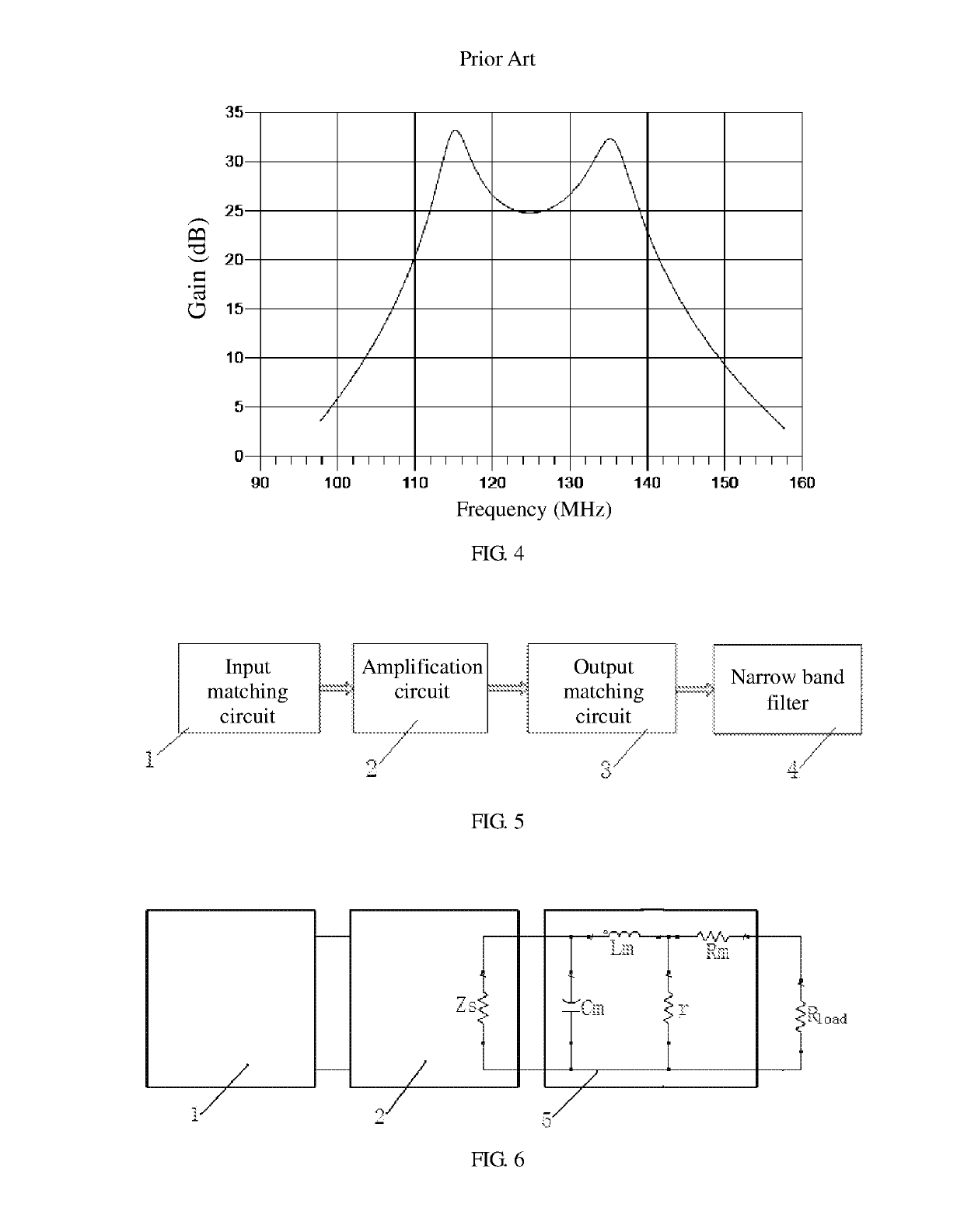
[0037]Please see FIG. 5, a pre-amplifier for a magnetic resonance imaging radio-frequency coil of the invention comprises an input matching circuit 1, an amplification circuit 2, an output matching circuit 3 and a narrow band filter 4 which are connected in sequence. A magnetic resonance signal is detected by the magnetic resonance imaging radio-frequency coil, input into the pre-amplifier for the magnetic resonance imaging radio-frequency coil of the invention through the input matching circuit 1 and input into a spectrometer and a computer after being subjected to impedance matching of the input matching circuit 1, amplification of the amplification circuit 2, secondary impedance matching of the output matching circuit 3 and filtering of the narrow band filter 4, so that a required image is generated. The input matching circuit 1, the amplification circuit 2 and the output matching circuit 3 are not improved in any form by the pre-amplifier for the magnetic resonance imaging radio...

second embodiment

[0043]Please see FIG. 6, the pre-amplifier for the magnetic resonance imaging radio-frequency coil of the invention comprises an input matching circuit 1, an amplification circuit 2, an output matching circuit 3 and a narrow band filter 4 which are connected in sequence, wherein the input matching circuit 1 and the amplification circuit 2 are both in existence, and the output matching circuit 3 and the narrow band filter 4 form an integrated circuit 5. The input matching circuit 1 is provided with a first output end and a second output end. The amplification circuit 2 comprises a first input end, a second input end, a first output end and a second output end. The first input end and the second input end of the amplification circuit 2 are connected with the first output end and the second output end of the input matching circuit 1 correspondingly. The amplification circuit 2 comprises an equivalent output impedor Zs, and the two ends of the equivalent output impedor Zs form the first...

third embodiment

[0046]Please see FIG. 9, the pre-amplifier for the magnetic resonance imaging radio-frequency coil of the invention comprises an input matching circuit 1, an amplification circuit 2, an output matching circuit 3 and a narrow band filter 4 which are connected in sequence. The input matching circuit 1, the amplification circuit 2 and the output matching circuit 3 are all in existence. The input matching circuit 1 is provided with a first output end and a second output end. The amplification circuit 2 comprises a first input end, a second input end, a first output end and a second output end. The first input end and the second input end of the amplification circuit 2 are connected with the first output end and the second output end of the input matching circuit 1 correspondingly. The amplification circuit 2 comprises an equivalent output impedor Zs, and the two ends of the equivalent output impedor Zs form the first output end and the second output end of the amplification circuit 2 co...


PUM


Abstract

A pre-amplifier for a magnetic resonance imaging radio-frequency coil. The pre-amplifier comprises an input matching circuit (1), an amplification circuit (2), an output matching circuit (3) and a narrow band filter (4) for filtering a magnetic resonance signal amplified through the amplification circuit (2). The present invention has the technical effect that the pre-amplifier for a magnetic resonance imaging radio-frequency coil generates a gain required by magnetic resonance imaging within a very small range near a magnetic resonance signal frequency point, but only generates a very small gain or has no amplification function completely at other frequency points, thereby significantly reducing the possibility of oscillation of the magnetic resonance imaging radio-frequency coil.

Description

[0001]This application is the U.S. national phase of International Application No. PCT / CN2015 / 078726 filed on 12 May 2015 which designated the U.S. and claims priority to Chinese Application Nos. CN 201410226536.5 filed on 27 May 2014, the entire contents of each of which are hereby incorporated by reference.TECHNICAL FIELD[0002]The invention relates to a pre-amplifier for a magnetic resonance imaging radio-frequency coil in the field of magnetic resonance imaging.BACKGROUND OF THE INVENTION[0003]Magnetic resonance imaging is an advanced human body non-invasive imaging technique and widely applied to diagnosis of diseases of all parts of the human body. A magnetic resonance imaging system comprises a magnetic resonance imaging radio-frequency coil, a pre-amplifier for the magnetic resonance imaging radio-frequency coil, and a magnet, a gradient and radio-frequency power amplifier, a spectrometer, a computer and other components. The structure of a magnetic resonance imaging radio-fr...

Claims


Application Information

Patent Timeline
Patent Type & Authority Patents(United States)
IPC IPC(8): G01R33/36H03F1/56H03H9/46H03F3/189G01R33/34
CPCG01R33/3614G01R33/34092G01R33/3621H03F1/565H03H9/46H03F3/189H03F2200/451H03F2200/171H03F2200/387
Inventor ZHANG, SONGTAOWANG, HAO
Owner SHANGHAI CHENGUANG MEDICAL TECH
Why Eureka
Try Eureka