
Automatic gain control circuit for receive apparatus for mobile object

a gain control circuit and receive apparatus technology, applied in the direction of gain control, transmission, transmission, etc., can solve the problems of affecting the operation of the receive apparatus, and the control range is limited to the output range so as to prevent the distortion of the output signal, and the gain of the variable gain amplifier can be held small

Active Publication Date: 2007-09-11
SEMICON COMPONENTS IND LLC
View PDF5 Cites 0 Cited by
  • Summary
  • Abstract
  • Description
  • Claims
  • Application Information

AI Technical Summary

Benefits of technology

The solution prevents signal distortion, stabilizes receive sensitivity, and broadens the control range, allowing for flexible design by maintaining a smaller gain during high signal inputs and swiftly responding to signal changes.

Problems solved by technology

Hence, when the received signal is large (at a large input), the gain of the variable gain amplifier VGA becomes large and the output signal thereof becomes distorted, thereby possibly causing the occurrence of interference on the receive apparatus side.
Furthermore, with the feed-back control scheme wherein the gain is adjusted according to the output of the variable gain amplifier VGA, the problem occurs that the control range is limited to the output range-of the variable gain amplifier.
Moreover, for example, in the case where the antenna is attached to a car, the intensity of the received signal possibly changes rapidly, and hence in the feed-back control scheme, the response may be delayed.

Method used


Image

  • Automatic gain control circuit for receive apparatus for mobile object
  • Automatic gain control circuit for receive apparatus for mobile object
  • Automatic gain control circuit for receive apparatus for mobile object

Examples


Embodiment Construction

[0025]At least the following matters will be made clear by the explanation in the present specification and the description of the accompanying drawings.

=== Outline ===

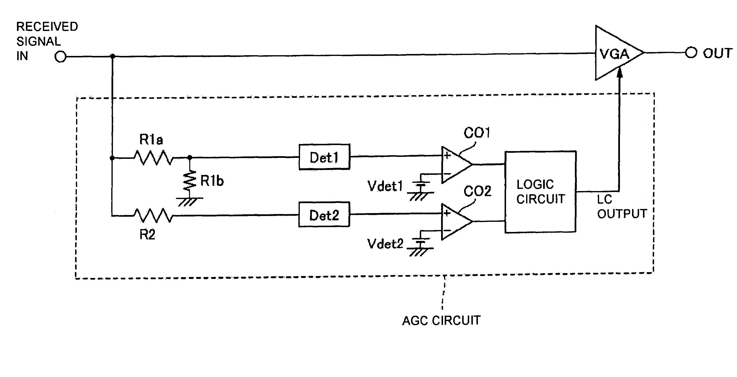
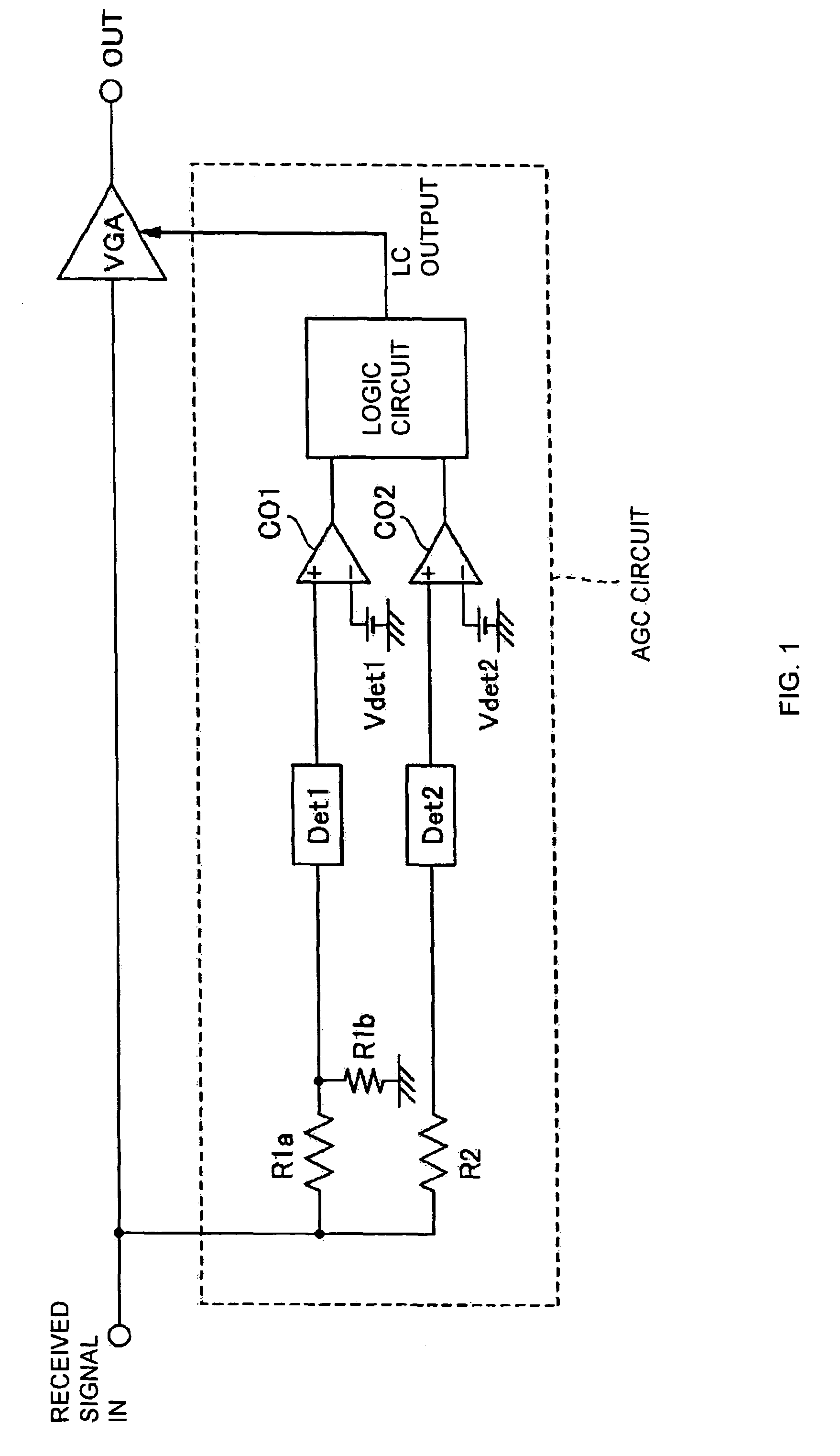
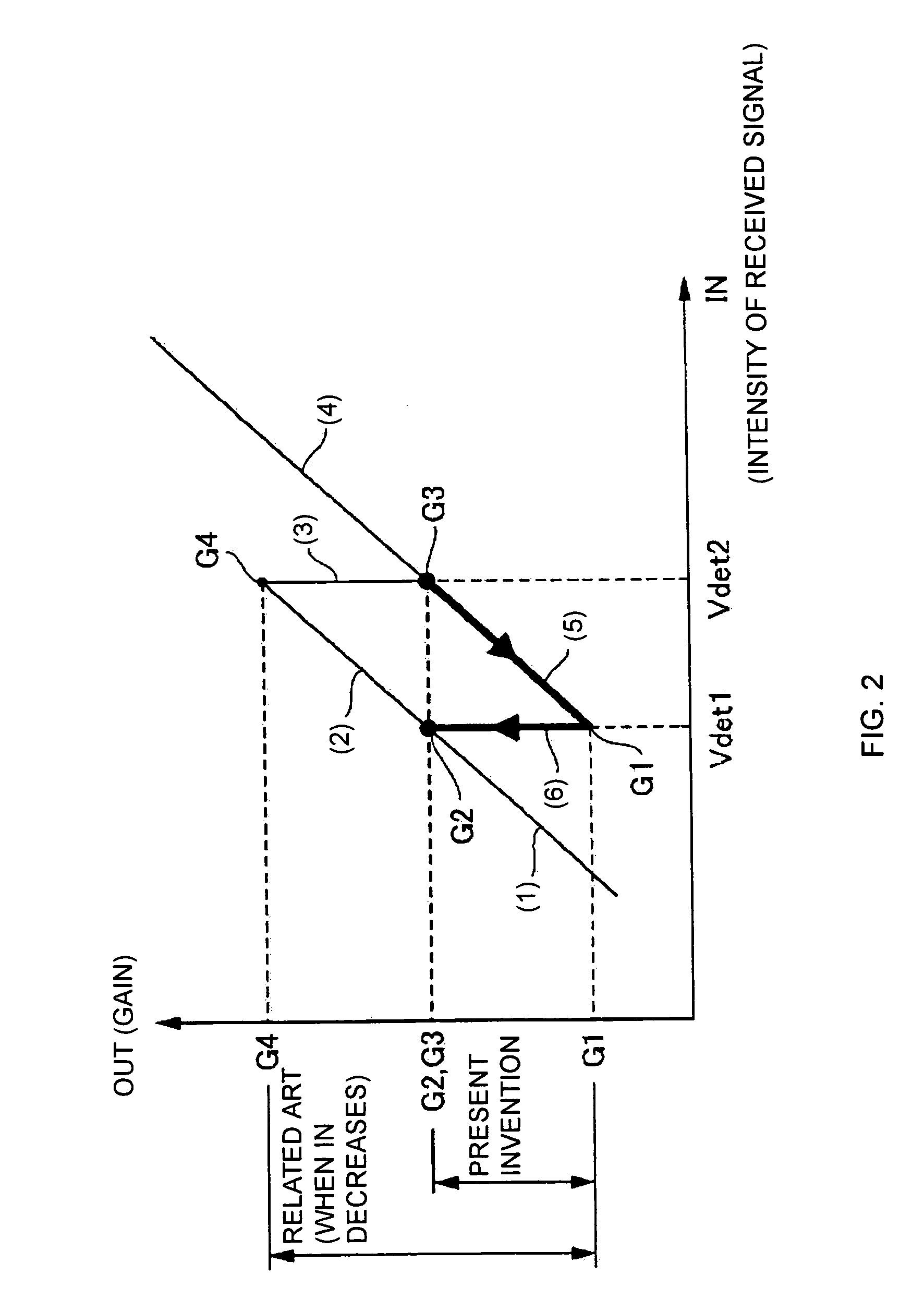
[0026]An embodiment of an automatic gain control circuit for a receive apparatus for a mobile object according to the present invention will be described with reference to FIGS. 1 to 4. As shown in the block diagram of FIG. 1, first, the AGC circuit is of a feed-forward control scheme that generates a control signal (LC output in the Figure) for adjusting the gain of a variable gain amplifier VGA based on a received signal IN of an antenna installed in a mobile object and the like and outputs the control signal to the variable gain amplifier VGA. Moreover, as described later with reference to FIG. 2, the AGC circuit operates such that the gain (output) of the variable gain amplifier VGA with respect to the intensity of the received signal (electrical field intensity) demonstrates a hysteresis.

=== Entire Details ===

[00...


PUM


Abstract

An automatic gain control circuit for a receive apparatus for a mobile object which automatically controls the gain of a variable gain amplifier amplifying a received signal from an antenna installed in the mobile object and outputting the amplified signal to the receive apparatus. The circuit comprises an intensity detector that detects an intensity of the received signal; a comparator that compares the detected intensity with first and second threshold voltages; and a controller that outputs a control signal for adjusting the gain to the variable gain amplifier based on the comparing results of the comparator so that the gain of the variable gain amplifier has a hysteresis with respect to the intensity of the received signal.

Description

CROSS-REFERENCE TO RELATED APPLICATIONS[0001]The present application claims priority upon Japanese Patent Application No. 2003-204278 filed on Jul. 31, 2003, which is herein incorporated by reference.BACKGROUND OF THE INVENTION[0002]1. Field of the Invention[0003]The present invention relates to an automatic gain control circuit for a receive apparatus for a mobile object.[0004]2. Description of the Related Art[0005]A car, for example, as a mobile object has an indoor-attachment-type, film-type antenna installed thereto. Along therewith, a variable gain amplifier (VGA) with an automatic gain control (AGC) circuit that amplifies the received signal of this antenna and outputs the signal to a general-purpose radio tuner and the like (receive apparatus) at the rear stage is installed in the car.[0006]This variable gain amplifier with the automatic gain control circuit has a well-known AGC circuit connected to the output of the variable gain amplifier VGA as shown in FIG. 5. This AGC ci...

Claims


Application Information

Patent Timeline
Patent Type & Authority Patents(United States)
IPC IPC(8): H04B7/00H04B1/06H04L27/06H03G1/00H03G3/20H03G3/30H04B1/16
CPCH03G1/0088H03G3/3036H04B1/16H04L27/06
Inventor SAEKI, TAKAO
Owner SEMICON COMPONENTS IND LLC
Learn More