Method for arranging a separating piston in a cavity and a device with such a separating piston

a technology of separating pistons and cavities, which is applied in the direction of springs, vibration dampers, accumulator installations, etc., to achieve the effect of facilitating non-critical setting of initial positions

Active Publication Date: 2011-07-12
OHLINS
View PDF12 Cites 44 Cited by
  • Summary
  • Abstract
  • Description
  • Claims
  • Application Information

AI Technical Summary

Benefits of technology

[0008]The objects of the present invention are, among other things, directed at providing an improved method of arranging a separating piston in a cavity and setting an initial position of the piston. Further, an object of the present invention is to facilitate non-critical setting of the initial position of the separating piston without draining liquid from the system. Accordingly, the separating piston can be given an initial position that takes into account any variations in pressure between the upper and lower sides of the separating piston resulting from the said temperature variations, leakage, etc.

Problems solved by technology

Setting the initial position of the separating piston in the cavity is critical and has hitherto involved a complicated method.

Method used


Image

  • Method for arranging a separating piston in a cavity and a device with such a separating piston
  • Method for arranging a separating piston in a cavity and a device with such a separating piston
  • Method for arranging a separating piston in a cavity and a device with such a separating piston

Examples


Embodiment Construction

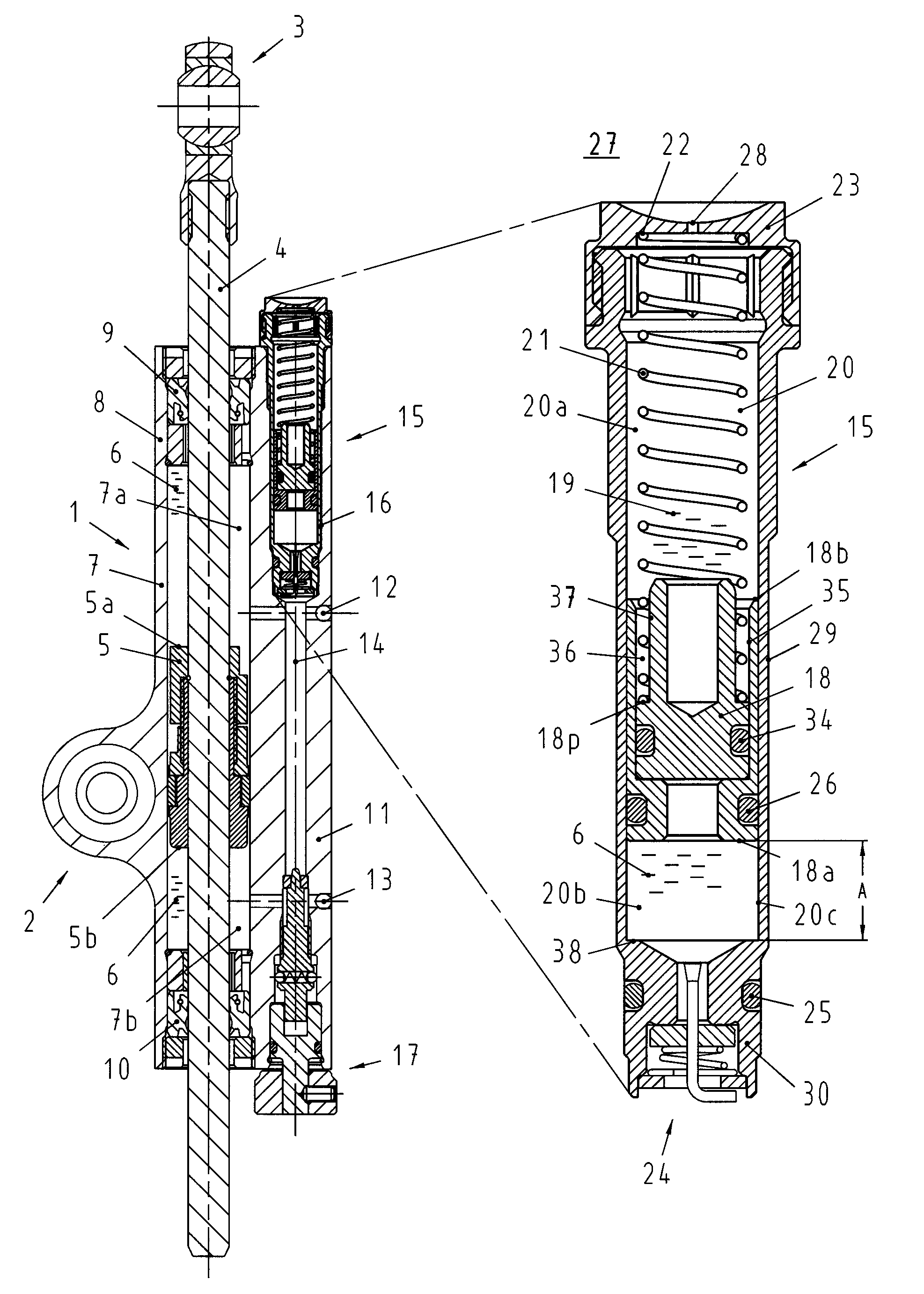
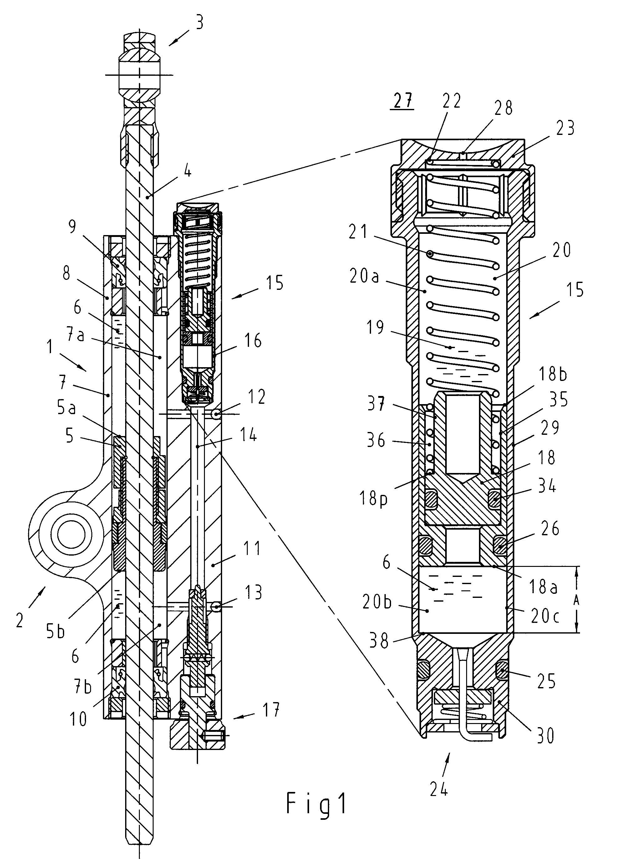
[0031]FIG. 1 shows an embodiment of a steering damper 1 that is arranged and configured in accordance with certain features, aspects and advantages of the present invention. The basic construction of the steering damper 1 can be of a known type and, for example, consists of the Ohlins SD100 or SD200 steering damper sold on the general market by the applicant of the present patent application.

[0032]The steering damper can comprise one or more mounting devices 2 for mounting the steering damper 1 onto the handlebars of a motorcycle, cycle, etc, (not shown in FIG. 1). In addition, other mounting devices 3 can be provided for mounting the steering damper 1 to the frame or chassis of the vehicle (not shown).

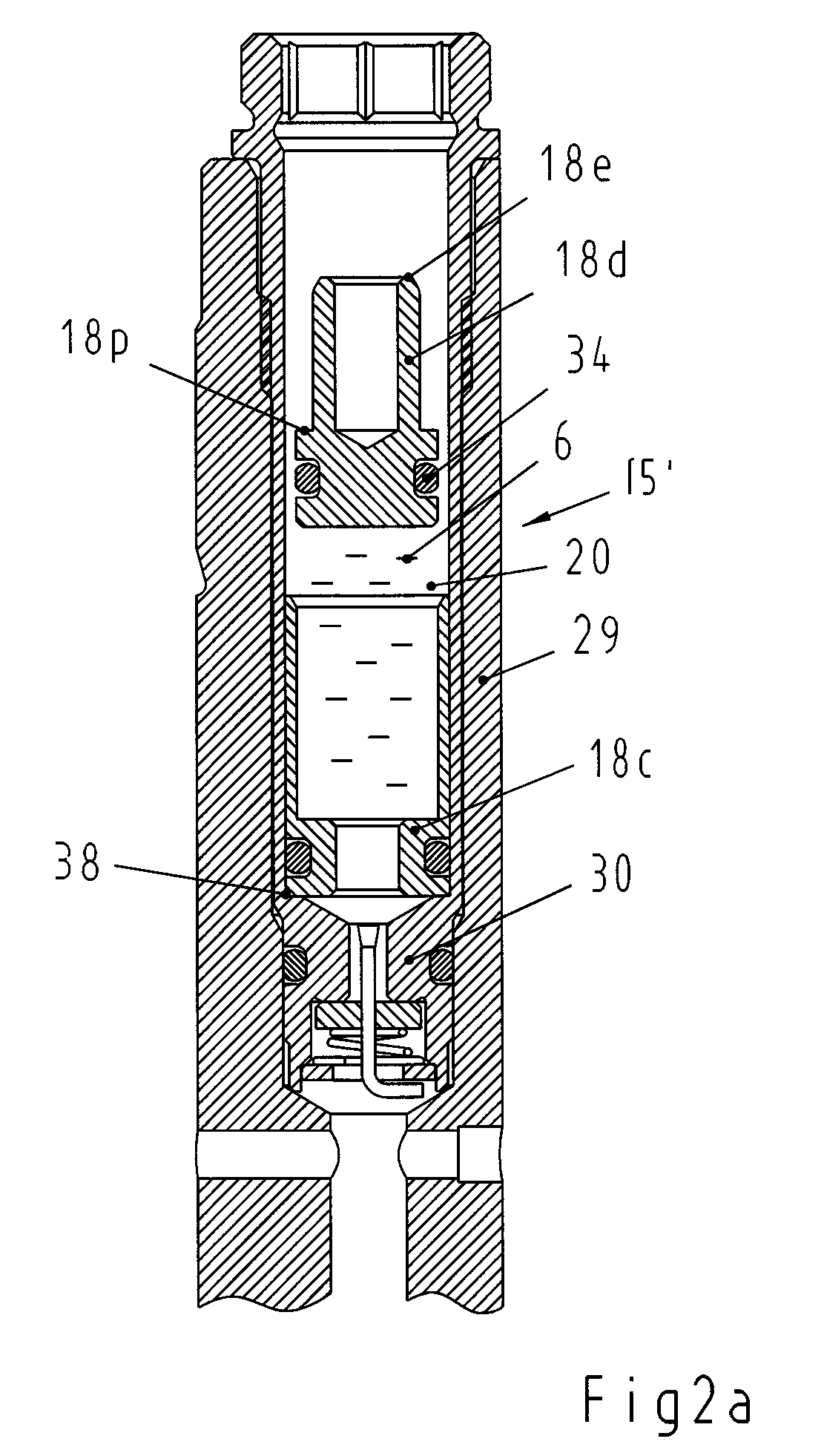
[0033]The steering damper preferably comprises a piston rod 4 extending in the longitudinal direction of the damper 1 that has a mounting device 3 at one end. A piston (or piston arrangement) 5 can be fixed on the piston rod 4. The piston 5 preferably operates in a liquid medium 6 tha...


PUM


Abstract

A steering damper system and method of regulating the fluid pressure of such a system are provided. The system can comprise a piston rod, a cylinder, a passage, and a damper portion. The damper portion can comprise a damper cavity, an outer piston, an inner piston, and a biasing component. The damper cavity can be in fluid communication with the passage. The outer piston can be slidably disposed in the damper cavity and define a chamber and a duct that is in fluid communication with the chamber and the passage. The inner piston can be slidably disposed in the chamber of the outer piston. The biasing component can exert an axial biasing force against the inner piston for regulating the pressure of fluid disposed in the system passing intermediate the passage, the damper cavity, and the chamber of the outer piston.

Description

CROSS REFERENCE TO RELATED APPLICATIONS[0001]This application claims the benefit and priority to and is a U.S. National Phase of PCT International Application Number PCT / SE2006 / 000951, filed on Aug. 17, 2006, designating the United States of America and published in the English language, which claims priority under 35 U.S.C. §119 to Swedish Application Number 0501836-1, filed on Aug. 19, 2005, the disclosures of the each of which are hereby incorporated by reference in their entireties.BACKGROUND OF THE INVENTION[0002]1. Field of the Invention[0003]The present invention relates, among other things, to a method for arranging a separating piston in a system cavity where a liquid medium is sealed off and separated from a second medium, for example, a gas, by means of the separating piston.[0004]The invention also relates to a device with a separating piston in a system cavity, for example, a steering damper cavity, where the piston seals off and separates a liquid medium from a second ...

Claims


Application Information

Patent Timeline
Patent Type & Authority Patents(United States)
IPC IPC(8): F16F9/00
CPCF15B1/021F16F9/3235F16F9/065F16F9/067F15B2201/21F15B2201/31F15B2201/61F15B2201/32F15B1/24F16F9/3271
Inventor SODERDAHL, JOHAN
Owner OHLINS
Why Eureka
Try Eureka