High pressure coring assembly and method

a coring and high-pressure technology, applied in the field of coring tools, can solve the problems of high surface pressure, difficult to achieve coring, and difficulty in achieving high-pressure coring, etc., and achieve the effect of accurate results and large cores

Active Publication Date: 2012-09-20
CORPRO TECH CANADA LTD
View PDF10 Cites 50 Cited by
  • Summary
  • Abstract
  • Description
  • Claims
  • Application Information

AI Technical Summary

Benefits of technology

[0018]It is an object of the present invention to provide an improved coring tool which provides larger cores and more accurate results even when working at significant depths and pressures.

Problems solved by technology

However, problems arise with conventional coring tools because many presently produced formations are at 10,000 feet and greater where pressures range from 7500-12000 psi.
However, such attempts have been unsuccessful due to numerous problems.
For example, after retrieval, the coring tool contained the very high and dangerous pressure on the surface.
This makes the coring tool difficult to handle and potentially quite dangerous to the drilling crew as the core is removed from the well.
In some cases, the valve may malfunction and is kept open or partially open by the core itself, thereby losing a significant amount of fluids and gases.
A malfunctioning valve might also suddenly release pressure at the surface, which could produce a dangerous high pressure spray.
This prior art design requires a high pressure chamber and high pressure valve, which results in greatly limiting the volume of the retrieved core so that only a one to two inch diameter core might be obtained from an eight and one half inch borehole.
As well, the cores from such tools were very short.
Smaller cores are inherently less desirable and / or reliable for calculations.
However, over the past years, new sources of natural gas formations have been developed at considerably greater depths and pressures for which the estimation calculations are no longer accurate.
Back calculating with any degree of accuracy from the 5% content remaining in the core is virtually impossible.

Method used


Image

  • High pressure coring assembly and method
  • High pressure coring assembly and method
  • High pressure coring assembly and method

Examples


Embodiment Construction

[0098]The present invention can be utilized to capture the fluid and gas of larger cores of shale formations taken at higher pressures and depths. Most of the shale gas reservoirs are at 7000 to 12000 psi.

[0099]In one embodiment, the present invention utilizes decreasing well bore drilling fluid pressure as the core moves up the wellbore to activate coring assembly mechanisms to collect all or essentially all the gas and liquids that are expelled while the core is tripped out of the hole.

[0100]In one embodiment, the present invention avoids the problem of holding the core at high reservoir pressures, which are dangerous at the surface.

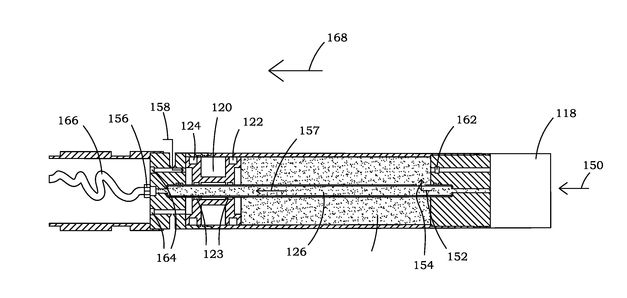
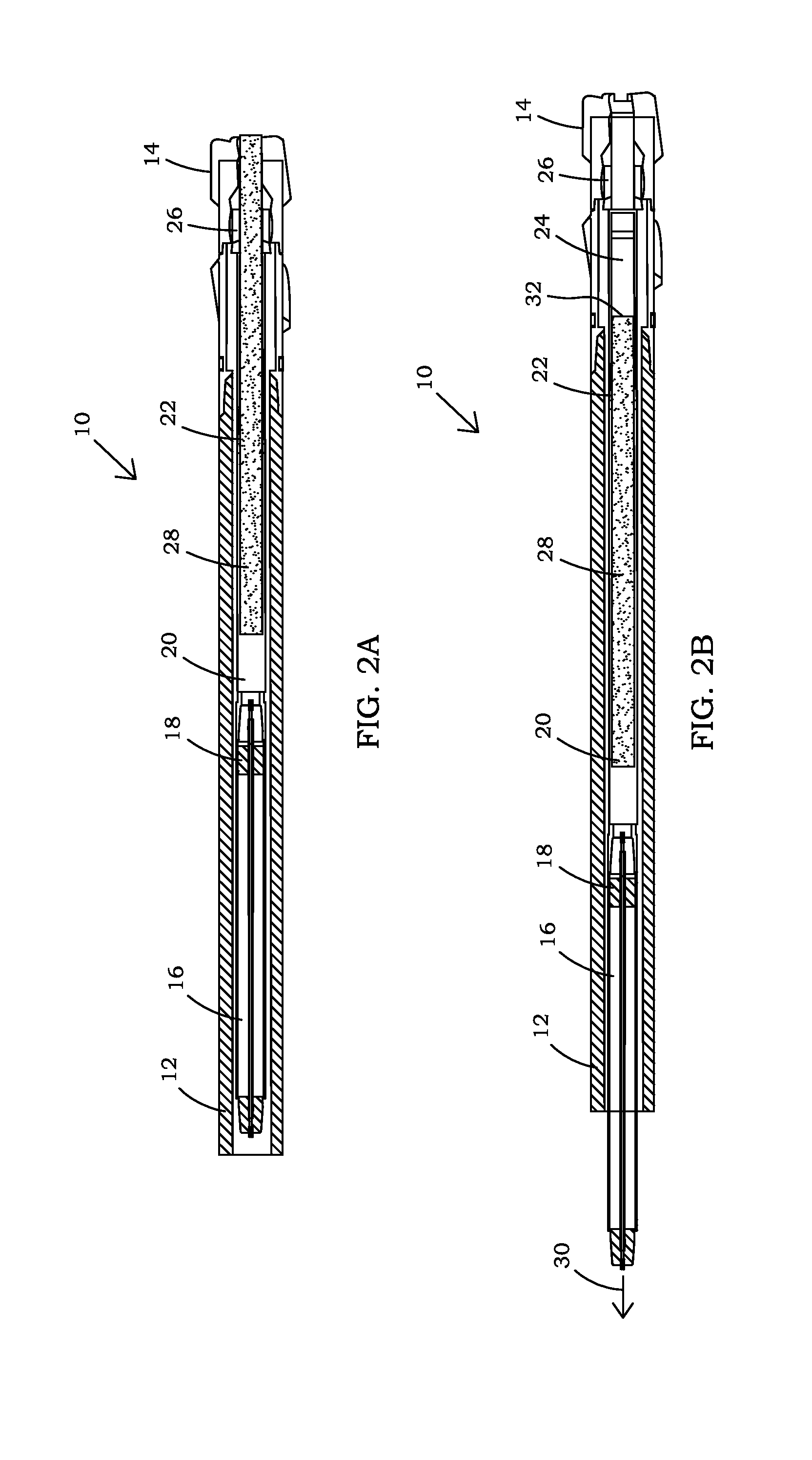
[0101]In one possible embodiment, the coring tool of the present invention provides a bottom valve mechanism which allows capturing the core and closing the bottom of the inner barrel after coring is completed. but prior to lifting off the bottom of the well bore.

[0102]Referring to FIG. 1A, there is shown an external view of one possible embodiment of ...


PUM

PropertyMeasurementUnit
pressuresaaaaaaaaaa
diameteraaaaaaaaaa
diameteraaaaaaaaaa

Abstract

A wireline or drill pipe retrievable coring tool with an inner barrel to receive a core, a bottom coring tool valve operable to seal off a bottom of the inner barrel and at least one pressure canister operable to receive fluid from the core in the inner barrel. The pressure canister is operable to significantly reduce the pressure inside the inner barrel utilizing an expandable chamber to receive fluid from the core as the tool is removed from the wellbore. In one embodiment, a bottom valve mechanism moves the cored formation materials out of the way of the bottom valve before the bottom valve is closed.

Description

[0001]This application claims benefit of U.S. patent application No. 61 / 453,232, filed Mar. 16, 2011 and U.S. patent application No. 61 / 559,967, filed Nov. 15, 2011. The above applications are incorporated herein by reference.BACKGROUND OF THE INVENTION[0002]1. Field of the Invention[0003]The present invention relates generally to coring tools and, more particularly, to a coring tool which provides a more accurate determination of the gas and liquids in the core even when the core is taken at significant depths and high pressure formations.[0004]2. Description of the Background[0005]The goal behind a pressure coring tool is to bring an in situ sample of the core to surface. Ideally, the core would still contain all of the gas and various fluids that the core originally contained when captured at reservoir pressure. If the core samples are the same as they were when captured, subsequent measurements can be used to estimate the reserve gas in the formation.[0006]However, problems aris...

Claims


Application Information

Patent Timeline
Patent Type & Authority Applications(United States)
IPC IPC(8): E21B10/02B23P11/00
CPCE21B21/10Y10T29/494E21B2034/005E21B25/00E21B25/02E21B2200/05
Inventor KINSELLA, DOUGLAS
Owner CORPRO TECH CANADA LTD
Why Eureka
Try Eureka