
Fiber amplifier system for suppression of modal instabilities and method

a fiber amplifier and fiber laser technology, applied in the field of high-power optical fiber amplifiers and lasers, can solve the problems of limiting the power scaling of the fiber laser output, modal instabilities (mi), and limitations of fiber lasers, and achieve the effects of avoiding or minimizing modal instabilities, minimizing modal distortions, and minimizing performan

Active Publication Date: 2015-12-15
LOCKHEED MARTIN CORP
View PDF24 Cites 7 Cited by
  • Summary
  • Abstract
  • Description
  • Claims
  • Application Information

AI Technical Summary

Benefits of technology

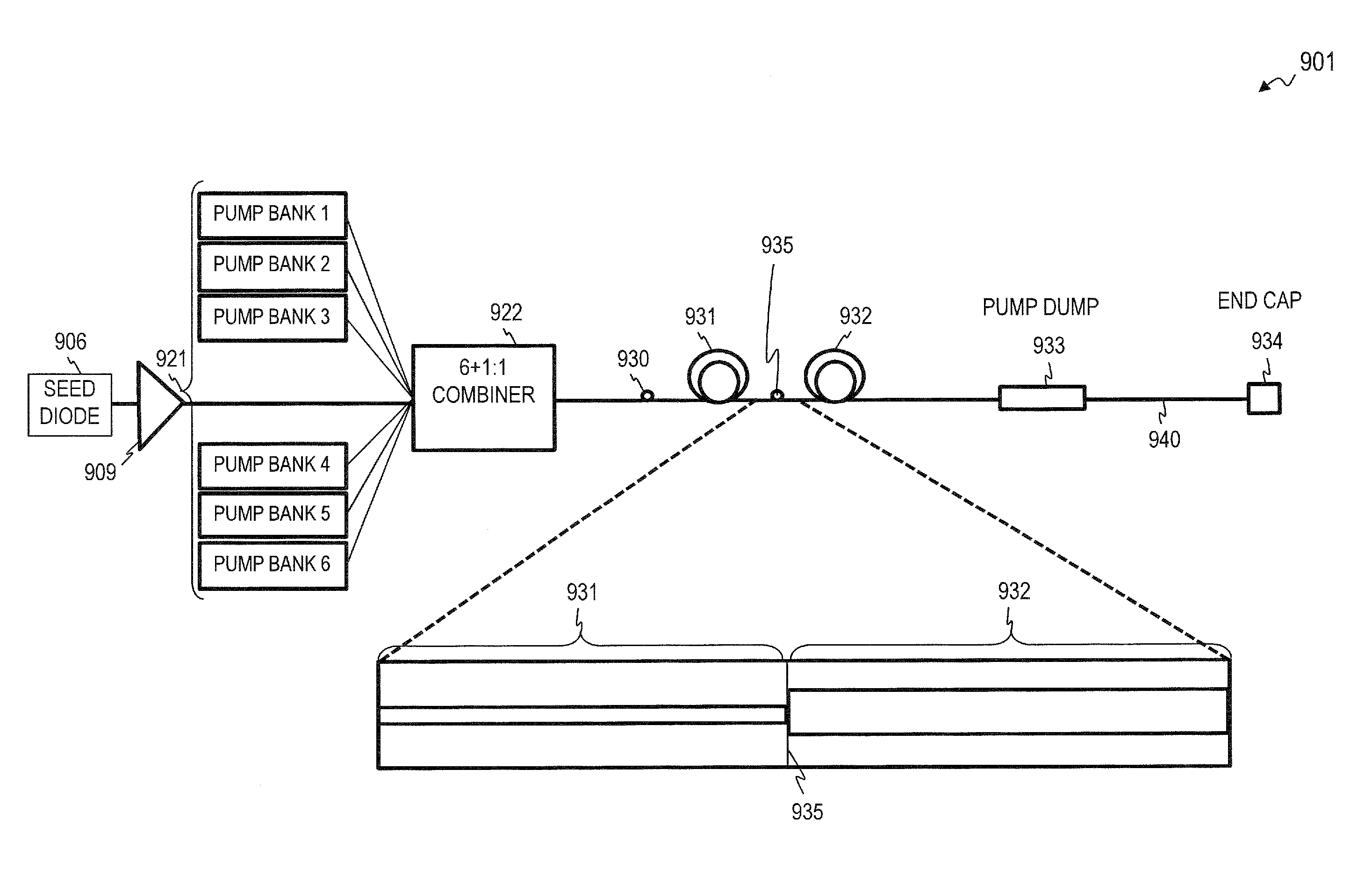
The present invention provides a solution for mitigating thermal effects in fiber amplifiers. It offers a hybrid fiber design with a smaller core at the initial length where the thermal load is highest, followed by a larger core for the remainder of the fiber length. This design avoids or minimizes modal instabilities while yielding almost the same performance as conventional fibers with regards to minimizing SBS. The hybrid fiber design also includes a fiber mandrel design that provides optimized cooling of the fiber and a fiber coil diameter that increases from the input to the output of the fiber such that modal distortions are minimized at the output end of the fiber where power levels are maximized. The present invention also optimizes the core / cladding diameter to balance the effects of thermal load and fiber length. Additionally, the present invention uses long-wavelength pumping to reduce quantum defect heating and pumps from both ends of the fiber amplifier to reduce the peak thermal load.

Problems solved by technology

The narrow linewidth and polarized output can limit power scaling of the fiber laser output due to a number of effects.
The limitations of fiber lasers include nonlinearities (e.g., Stimulated Brillouin Scattering (SBS)) and Modal Instabilities (MI).
For example, in some cases, modal instabilities in Large-Mode-Area (LMA) high-power fiber amplifiers limit power scaling from individual fibers.
In some cases, this transfer to higher order mode(s) may result in light being coupled out of the core into the fiber cladding, limiting output power.
The beam quality enhancement capability of the tested fibers was inconclusive due to incomparable launching conditions of the signal to the fibers.

Method used


Image

  • Fiber amplifier system for suppression of modal instabilities and method
  • Fiber amplifier system for suppression of modal instabilities and method
  • Fiber amplifier system for suppression of modal instabilities and method

Examples


Embodiment Construction

[0067]Although the following detailed description contains many specifics for the purpose of illustration, a person of ordinary skill in the art will appreciate that many variations and alterations to the following details are within the scope of the invention. Very narrow and specific examples are used to illustrate particular embodiments; however, the invention described in the claims is not intended to be limited to only these examples, but rather includes the full scope of the attached claims. Accordingly, the following preferred embodiments of the invention are set forth without any loss of generality to, and without imposing limitations upon the claimed invention. Further, in the following detailed description of the preferred embodiments, reference is made to the accompanying drawings that form a part hereof, and in which are shown by way of illustration specific embodiments in which the invention may be practiced. It is understood that other embodiments may be utilized and s...


PUM


Abstract

Apparatus and method for suppressing modal instabilities (MI) in fiber-amplifier systems. In some embodiments, thermal effects drive the MI process, and in some such embodiments, the present invention provides a plurality of options for mitigating these thermal effects. In some embodiments, the present invention provides a hybrid fiber with a smaller core in the initial length where the thermal loads are highest, followed by a larger-core fiber. In some embodiments the length of the smaller-core section is chosen to keep the core heat-per-unit-length of the second section below a critical value for the onset of MI. In some embodiments, the hybrid fiber of the present invention avoids modal instabilities while yielding almost the same performance as compared to conventional fibers with regard to minimizing fiber nonlinearities such as Stimulated Brillouin Scattering (SBS). In some embodiments, the hybrid fiber outputs a signal beam with at least 1 kW of power.

Description

CROSS-REFERENCE TO RELATED APPLICATIONS[0001]This invention is related to:[0002]U.S. Pat. No. 7,391,561 issued Jun. 24, 2008 to Fabio Di Teodoro et al., titled “FIBER- OR ROD-BASED OPTICAL SOURCE FEATURING A LARGE-CORE, RARE-EARTH-DOPED PHOTONIC-CRYSTAL DEVICE FOR GENERATION OF HIGH-POWER PULSED RADIATION AND METHOD,”[0003]U.S. Pat. No. 7,768,700 issued Aug. 3, 2010 to Matthias P. Savage-Leuchs, titled “METHOD AND APPARATUS FOR OPTICAL GAIN FIBER HAVING SEGMENTS OF DIFFERING CORE SIZES,”[0004]U.S. Pat. No. 7,876,803 issued Jan. 25, 2011 to Fabio Di Teodoro et al., titled “HIGH-POWER, PULSED RING FIBER OSCILLATOR AND METHOD,”[0005]U.S. Patent Application Publication 2011 / 0122895 published May 26, 2011 by Matthias P. Savage-Leuchs et al., titled “Q-SWITCHED OSCILLATOR SEED-SOURCE FOR MOPA LASER ILLUMINATOR METHOD AND APPARATUS” (which issued as U.S. Pat. No. 8,934,509 on Jan. 13, 2015),[0006]U.S. Pat. No. 8,441,718 issued May 14, 2013 by Roy D. Mead, titled “SPECTRALLY BEAM COMBINED L...

Claims


Application Information

Patent Timeline
Patent Type & Authority Patents(United States)
IPC IPC(8): H01S3/067G02B6/02G02B6/024H01S3/042H01S3/094H01S3/16H01S3/0941
CPCH01S3/042H01S3/06758H01S3/094007H01S3/06704H01S3/06712H01S3/06733H01S3/06745H01S3/09415H01S3/1618H01S2301/02H01S2301/03H01S3/1028
Inventor HONEA, ERIC C.SAVAGE-LEUCHS, MATTHIAS P.COURTNEY, SEAN M.BRAR, KHUSHVINDER S.HENRIE, JASON D.DILLEY, CHRISTIAN D.
Owner LOCKHEED MARTIN CORP
Learn More