Implant of low radial strength

a technology of radial strength and implant, which is applied in the field of endovascular implants, can solve problems such as cutting the ground away, and achieve the effect of better adapting to the pathological circumstances

Active Publication Date: 2006-03-23
BIOTRONIK AG
View PDF6 Cites 55 Cited by
  • Summary
  • Abstract
  • Description
  • Claims
  • Application Information

AI Technical Summary

Benefits of technology

[0008] An aspect of the present invention was to provide an endovascular implant which is better adapte...

Problems solved by technology

Clearly however, a very high level of radial strength for the stent is not advantageous for all lesions, but, by virtue of the high mechanical loading that this entails on the vessel wall and the ...

Method used


Image

  • Implant of low radial strength
  • Implant of low radial strength
  • Implant of low radial strength

Examples


embodiment 1

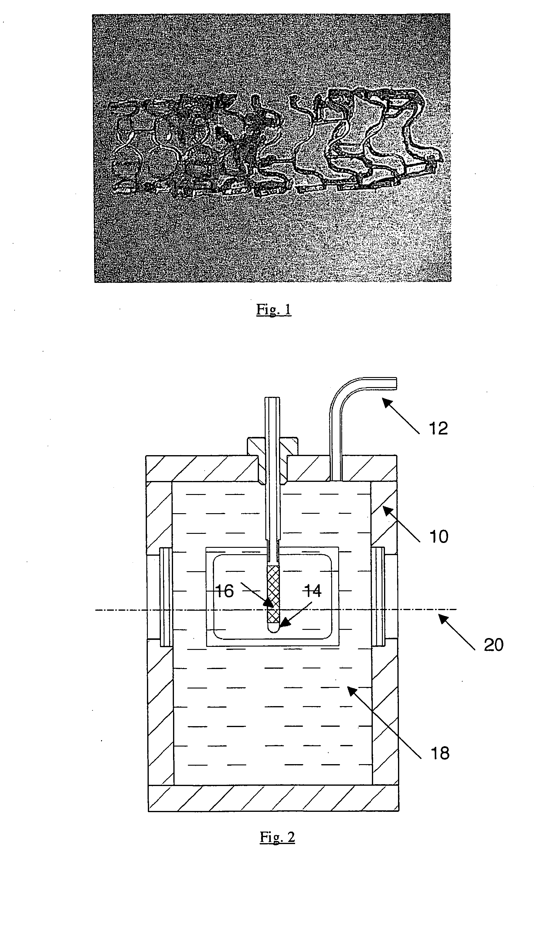
[0036] Sterilized stents comprising the in vivo degradable magnesium alloy WE43 were investigated. The stents were serially numbered for the investigations (Nos 1-14). The stents were of a diameter of 3.0 mm and stents Nos. 1, 3 and 5 were of a length of 15 mm while stents Nos. 2, 4 and 6 through 14 were of a length of 10 mm.

[0037] The radial strength of the degradable stents was investigated after storage in a corrosive environment. For that purpose, after a defined storage time, the compression pressure was measured as a measurement in respect of radial strength.

[0038] Before being put into storage in the test medium, the test objects which are in the form of bare stents were implanted into sterilized polyurethane hoses (inside diameter 3 mm, wall gauge 0.075 mm, sterilization with formaldehyde vapor (FAD) with an inwardly disposed distal sleeve (Teflon). Implantation was effected manually under sterile laminar flow conditions.

[0039] Firstly the stent was removed from the speci...

embodiment 2

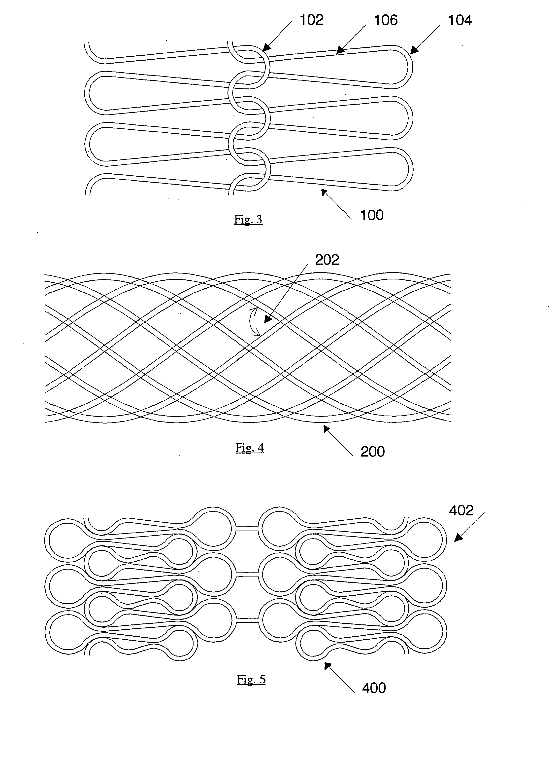
[0053]FIG. 3 shows a portion from a development of a stent illustrating a balloon-expandable structure 100 on a wire basis, which is composed of a multiplicity of individual ring segments. No transverse forces are transmitted by the flexible connection 102 of the individual ring segments, even in the case of curved vessels. The bending radius 104 is adapted to the material properties and the desired maximum opening diameter. The length of the element 106, together with the wire diameter, determines the radial strength. In particular the biodegradable magnesium alloy WE43 is suitable as the material.

embodiment 3

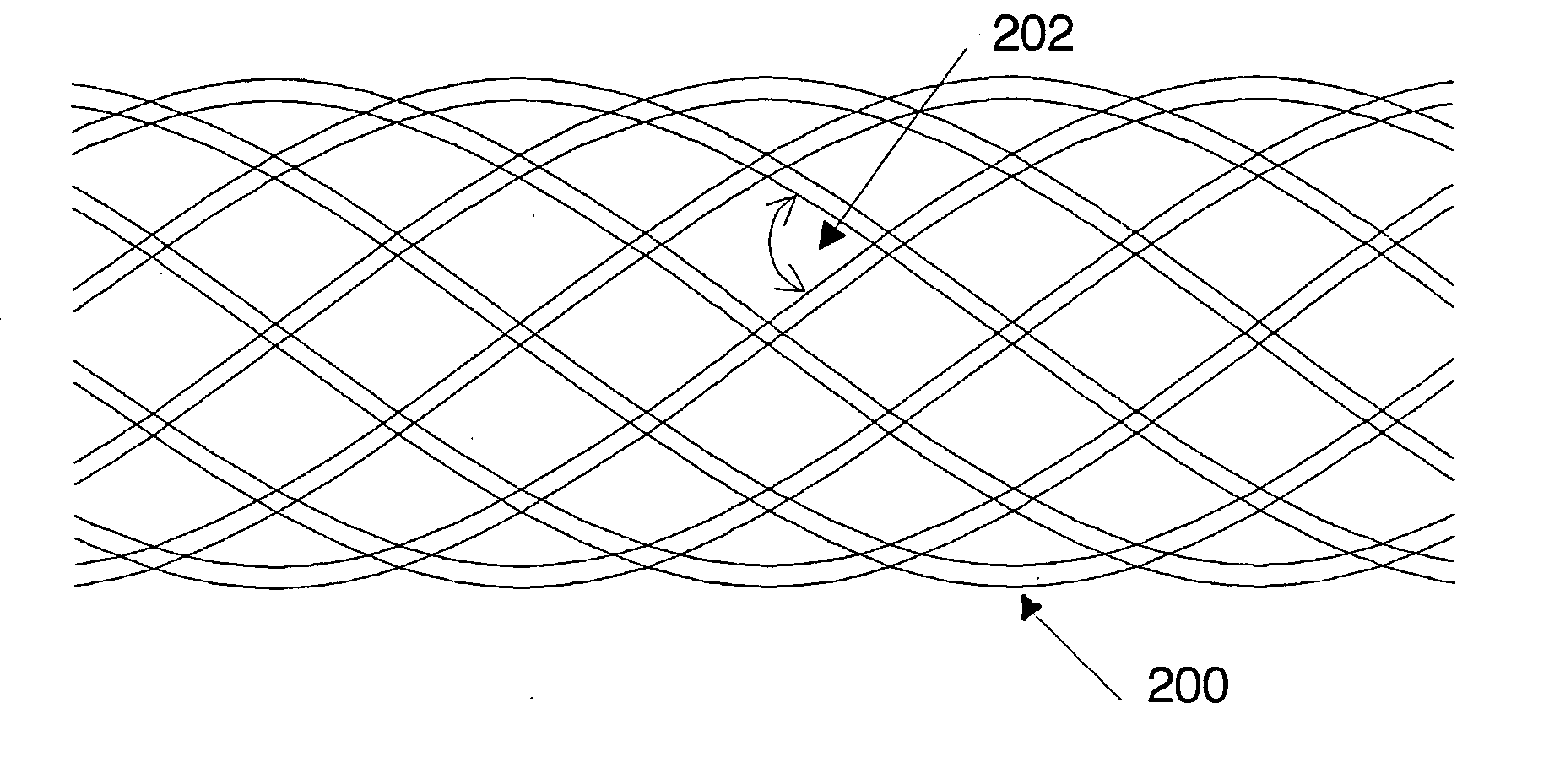
[0054]FIG. 4 shows a self-expandable structure 200 on a wire basis.

[0055] Described hereinafter are various measures in terms of the stent design, by means of which the radial strength can be set to the range of values according to the invention. The measures are based on established theoretical considerations and are familiar to the individual skilled in the art per se so that the practical implementation thereof can be effected at a low level of experimental complication and expenditure. The measures are to be respectively matched to each other, so as to give a radial strength in the desired value range.

[0056] A first measure provides that a biodegradable material with a low modulus of elasticity is used. By way of example, the magnesium alloy WE43 with a modulus of elasticity of approximately 45,000 MPa presents itself as being suitable. If the illustrated structure is wound from twenty wires of a wire diameter of 0.09 mm, at an angle 202 of 110°, to form a stent of diameter of...


PUM


Abstract

The invention concerns an endovascular implant comprising a biodegradable material and having a tubular main body which is open at the ends and which is dilatable from an unexpanded condition into an expanded condition. The implant is so designed that when the implant in the expanded condition is subjected to a radially acting compression pressure in the range of between 5 and 30 kPa (0.05-0.3 bar) a cross-sectional area of the implant is reduced to 70% or less of the original cross-sectional area, or an internal volume of the implant is reduced to 70% or less of the original internal volume.

Description

BACKGROUND OF THE INVENTION [0001] The invention concerns an endovascular implant comprising a tubular main body which is open at the ends and which is dilatable from an unexpanded condition into an expanded condition. [0002] The implantation of endovascular support systems has been established for many years in medical technology as one of the most effective therapeutic measures in the treatment of vascular diseases. Thus for example, the introduction of stents in interventional therapy in respect of stable and unstable angina pectoris has resulted in a marked reduction in the rate of re-stenoses and thus better long-term results. The cause of using stent implantation in the above-indicated indication is the higher level of primary lumen gain. Admittedly, the use of stents makes it possible to achieve an optimum vessel cross-section which is primarily necessary for therapy success, but it will be noted that the permanent presence of a foreign body of that kind injects a cascade of ...

Claims


Application Information

Patent Timeline
IPC IPC(8): A61F2/06A61F2/86A61F2/90A61F2/91
CPCA61F2/86A61L31/022A61F2/91A61F2/90
Inventor GEROLD, BODOHARDER, CLAUSHEUBLEIN, BERNDMUELLER, HEINZHEUBLEIN, EVAHEUBLEIN, NORAHEUBLEIN, CHRISTOPH
Owner BIOTRONIK AG
Why Eureka
Try Eureka