Stabilized equipment support and method of balancing same

a technology of equipment support and stabilization, which is applied in the direction of machine support, television system, instruments, etc., can solve the problems of unsatisfactory approaches, undesirable motions of the camera along the pan and/or tilt and/or roll axes, and the equipment weight is low

Active Publication Date: 2011-07-12
THE TIFFEN
View PDF14 Cites 6 Cited by
  • Summary
  • Abstract
  • Description
  • Claims
  • Application Information

AI Technical Summary

Benefits of technology

[0010]One aspect of this invention is directed to a stabilized support for supporting motion-sensitive equipment, especially an ultra-lightweight camera, and for isolating the equipment from unwanted motion. The stabilized support includes a platform on which the equipment is mounted, and a structure on which the platform is detachably mounted. The structure includes a handle to be gripped and held by a human operator, a counterweight mounted below the platform, and an arcuate arm for connecting the handle with the counterweight. A plurality of ballast weights is supported by the platform to balance the support about its center of gravity. The ballast weights add weight to an upper portion of the support, and thus compensate for the very low weight of the equipment.
[0011]Preferably, the platform has an interior, and the ballast weights are mounted in the interior of the platform. The platform advantageously has a plurality of interior compartments, preferably arranged in generally parallel rows at opposite sides of the platform, each row extending in opposite directions fore and aft of the center of gravity. Each ballast weight is held and confined in a selected individual compartment. The interior confinement of the ballast weights prevents them from shifting and detachment, especially when the camera is moved, especially when turned upside down during operation, and / or when the operator is ambulatory. In addition, by placing the ballast weights fore and aft of the center of gravity, a measure of rotational stability is added.
[0012]It is further advantageous if a mounting plate is fixed to the equipment. The equipment and the plate are jointly removably and adjustably mounted on the platform. This enables the equipment to be readily mounted on, and detached from, the platform. In a preferred embodiment, the mounting plate has a trapezoidal cross-section, and the platform has a trapezoidal channel of complementary contour to the plate for slidably receiving the plate in a dovetail joint. In the event that the equipment has a control, such as a slide switch for releasing a battery for powering the equipment, and if the fixed mounting plate covers that control in certain versions of the equipment, then another aspect of this invention proposes configuring the mounting plate with a pair of hinged plate portions movable relative to each other. Thus, one of the plate portions can be pivoted away from blocking the control to enable ready access to the control without removing the plate from the equipment when, for example, the battery needs replacement.
[0014]A pair of foldable legs is optionally mounted on the arm for supporting the stabilized support on a support surface when the stabilized support is to be used as a tripod, or not in ambulatory use. Thus, the stabilized support may be supported by the handle or by the legs. The handle preferably has a virtually friction-free, three-axis, ball bearing gimbal that is indexably lockable and threaded into the coupler. The handle can engage a mounting notch for convenient fold-up storage during transport or equipment storage.
[0018]Thus, the balancing procedure is no longer performed while holding the support or its component parts in one's unsteady hand, but instead, is performed while balancing the support and / or its component parts relative to a stationary horizontal support surface. The operator's hand is no longer fatigued during the balancing procedure. This avoids the prior art's problems of instability, fatigue and unsteadiness of one's hand that prevents an accurate balance from being obtained.

Problems solved by technology

Still picture and motion picture (video) cameras have, at some time during their use, been held by a human operator whose inherent instability tended to produce blurred still and moving images.
The center of gravity laid within the camera and, by holding the camera at its exterior surface, the operator's inevitable unsteady hand motions exerted forces in directions effectively tangential to the camera's center of gravity, thereby resulting in undesirable motions of the camera along the pan and / or tilt and / or roll axes.
However, neither of these approaches were altogether satisfactory when the camera operator was ambulatory.
Hence, it was believed that the lighter the camera, the less useful such an equipoising support would be.
In addition to the traditional unsteadiness of a handheld camera, these handheld devices were being operated by amateur photographers, still further resulting in unstable and often unacceptable still and video images, especially during ambulatory operation.
However, in practice, the counterweight was often too light, or too close to the overhead camera, and the resulting support was imbalanced.
However, attaching such small weights to the counterweight made the equipoising support bottom heavy, and attaching such small weights to each camera was a cumbersome, laborious balancing procedure, typically performed while holding the support in one's unsteady and fatigued hand.
In any event, there was always the possibility that the attached weights could shift in position, or even become detached, when the camera operator was ambulatory.

Method used


Image

  • Stabilized equipment support and method of balancing same
  • Stabilized equipment support and method of balancing same
  • Stabilized equipment support and method of balancing same

Examples


Embodiment Construction

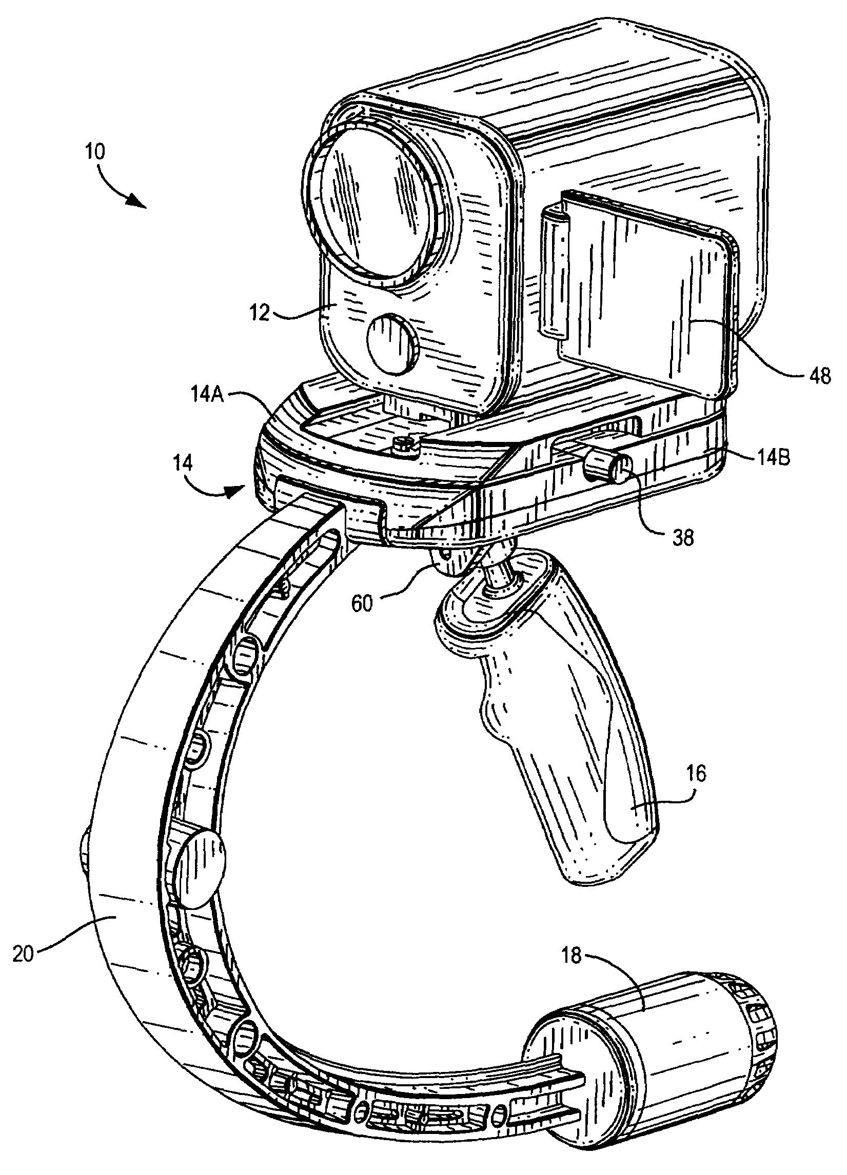
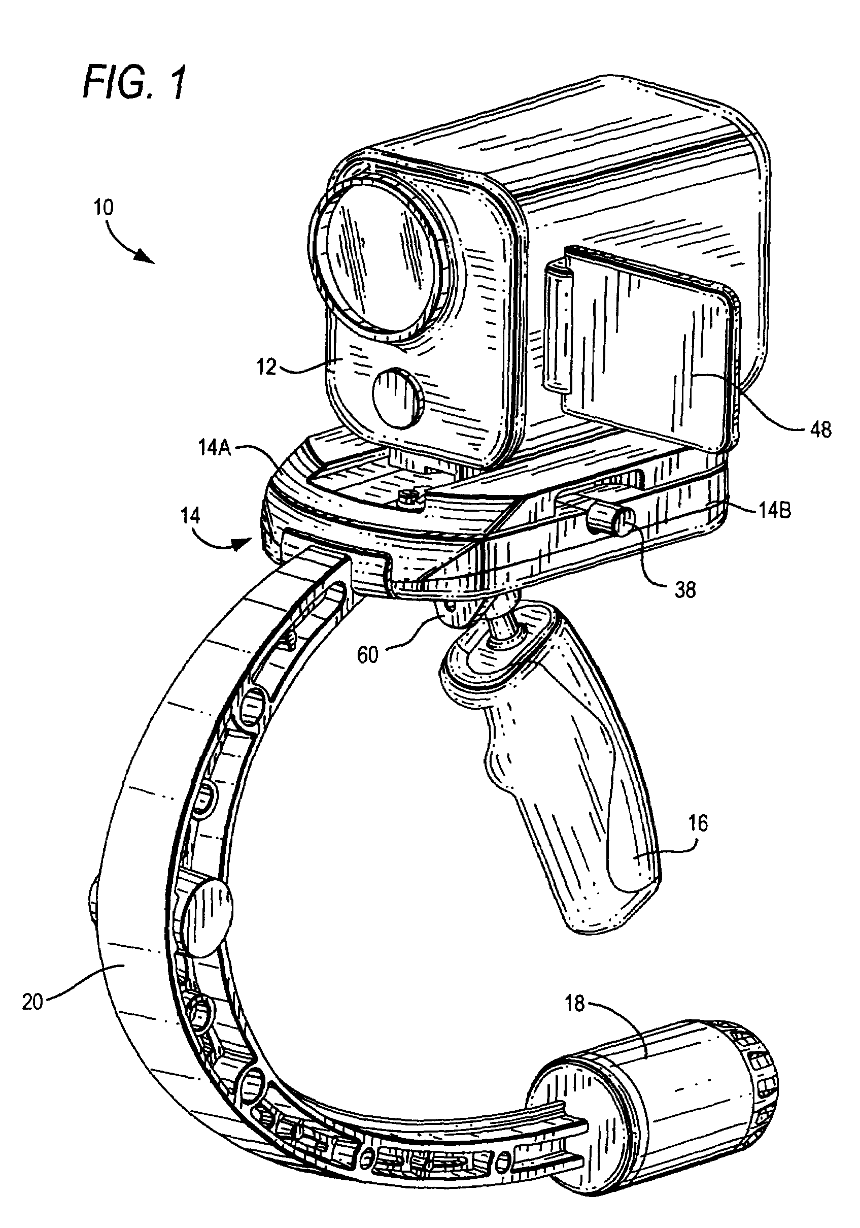
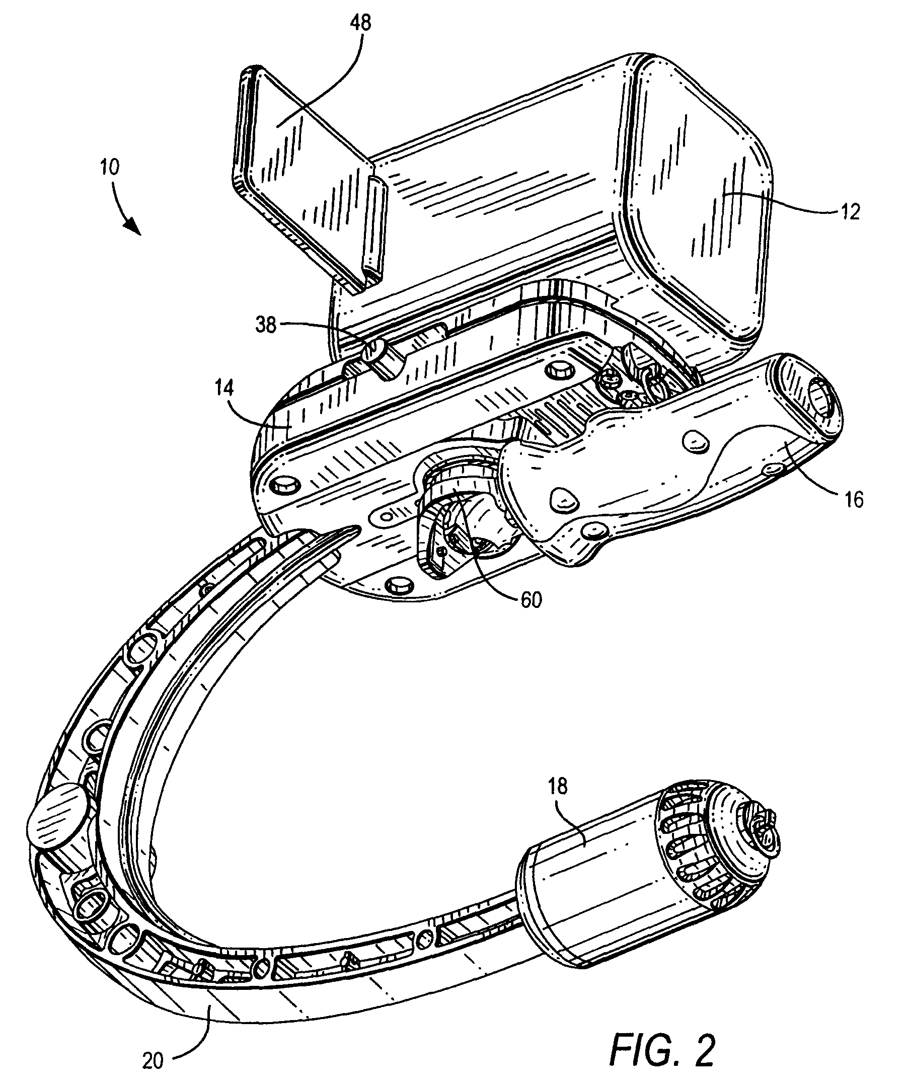
[0039]Referring now to the drawings, reference numeral 10 generally identifies a stabilized support for supporting motion-sensitive equipment 12, especially an ultra-lightweight still or video, digital camera, and for isolating the equipment 12 from unwanted motion. As shown in FIGS. 1-2, the stabilized support 10 includes a hollow platform 14 on which the equipment 12 is mounted, and a structure on which the platform 14 is detachably mounted. The structure includes a handle 16 for holding by a human operator, an adjustable counterweight 18 mounted below the platform 14, and an arcuate arm 20 having discrete weights therealong for connecting the handle 16 with the counterweight 18. A plurality of ballast weights 22, as best seen in FIG. 3, is supported by the platform 14 to balance the support 10 about a center of gravity. The ballast weights 22 not only add weight to an upper portion of the support 10, but also add rotational stability, and thus compensate for the very low weight o...


PUM


Abstract

A stabilized support for supporting motion-sensitive, ultra-lightweight, camera equipment includes a hollow platform on which the camera equipment is mounted, and a structure on which the platform is detachably mounted. The structure has a handle, a counterweight mounted below the platform, and an arm for connecting the handle with the counterweight. The platform has a plurality of interior compartments preferably arranged in generally parallel rows at opposite sides of the platform, each row extending past a center of gravity. A plurality of ballast weights is held and confined in the interior compartments within the platform to balance the support when held by the handle, or supported by optional support legs. The placement of the ballast weights is based on a balancing procedure in which the camera equipment is balanced relative to a stationary horizontal support surface.

Description

[0001]This application claims the priority of U.S. provisional patent application Ser. No. 61 / 142,503, filed Jan. 5, 2009.BACKGROUND OF THE INVENTION[0002]This invention generally relates to a stabilized equipment support and a method of balancing the same and, more particularly, to supporting ultra-lightweight cameras or other motion-sensitive equipment to isolate such equipment from unwanted motion during use.[0003]Still picture and motion picture (video) cameras have, at some time during their use, been held by a human operator whose inherent instability tended to produce blurred still and moving images. The center of gravity laid within the camera and, by holding the camera at its exterior surface, the operator's inevitable unsteady hand motions exerted forces in directions effectively tangential to the camera's center of gravity, thereby resulting in undesirable motions of the camera along the pan and / or tilt and / or roll axes.[0004]One approach to solving such motion problems w...

Claims


Application Information

Patent Timeline
Patent Type & Authority Patents(United States)
IPC IPC(8): G03B17/00H04N5/225
CPCF16M11/04F16M13/04F16M13/00F16M11/041G03B17/563G03B17/566F16F15/28F16M11/10
Inventor ORF, HANS ROBERTRUSH, FRANK A
Owner THE TIFFEN
Why Eureka
Try Eureka