Image capturing apparatus, its controlling method, and program

a technology of image capturing and control method, which is applied in the direction of color television details, television systems, instruments, etc., can solve the problems of difficult to verify the goodness/badness of the object image using such display units, and the position in which the focus was actually adjusted becomes uncertain,

Inactive Publication Date: 2011-07-12
CANON KK
View PDF4 Cites 13 Cited by
  • Summary
  • Abstract
  • Description
  • Claims
  • Application Information

AI Technical Summary

Problems solved by technology

However, due to space and cost restrictions, display unit such as LCD (liquid crystal display) monitor used in these cameras are limited in size.
Thus, it has been quite difficult to verify goodness / badness of the object image using such display units.
Therefore, when focus condition is checked, the position in which the focus was actually adjusted becomes uncertain.

Method used


Image

  • Image capturing apparatus, its controlling method, and program
  • Image capturing apparatus, its controlling method, and program
  • Image capturing apparatus, its controlling method, and program

Examples


first embodiment

The first embodiment will be explained using FIG. 1 to FIG. 8B.

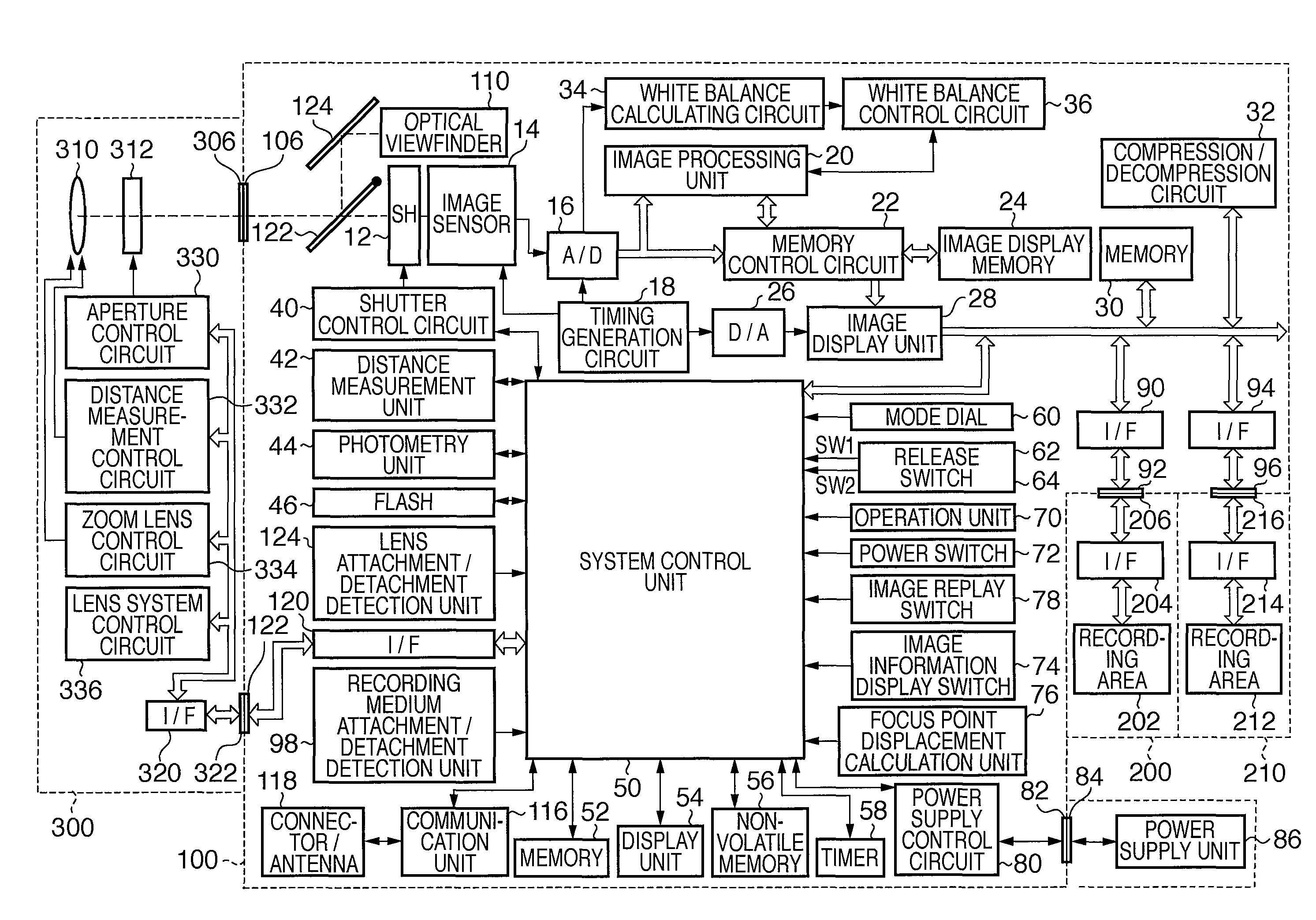
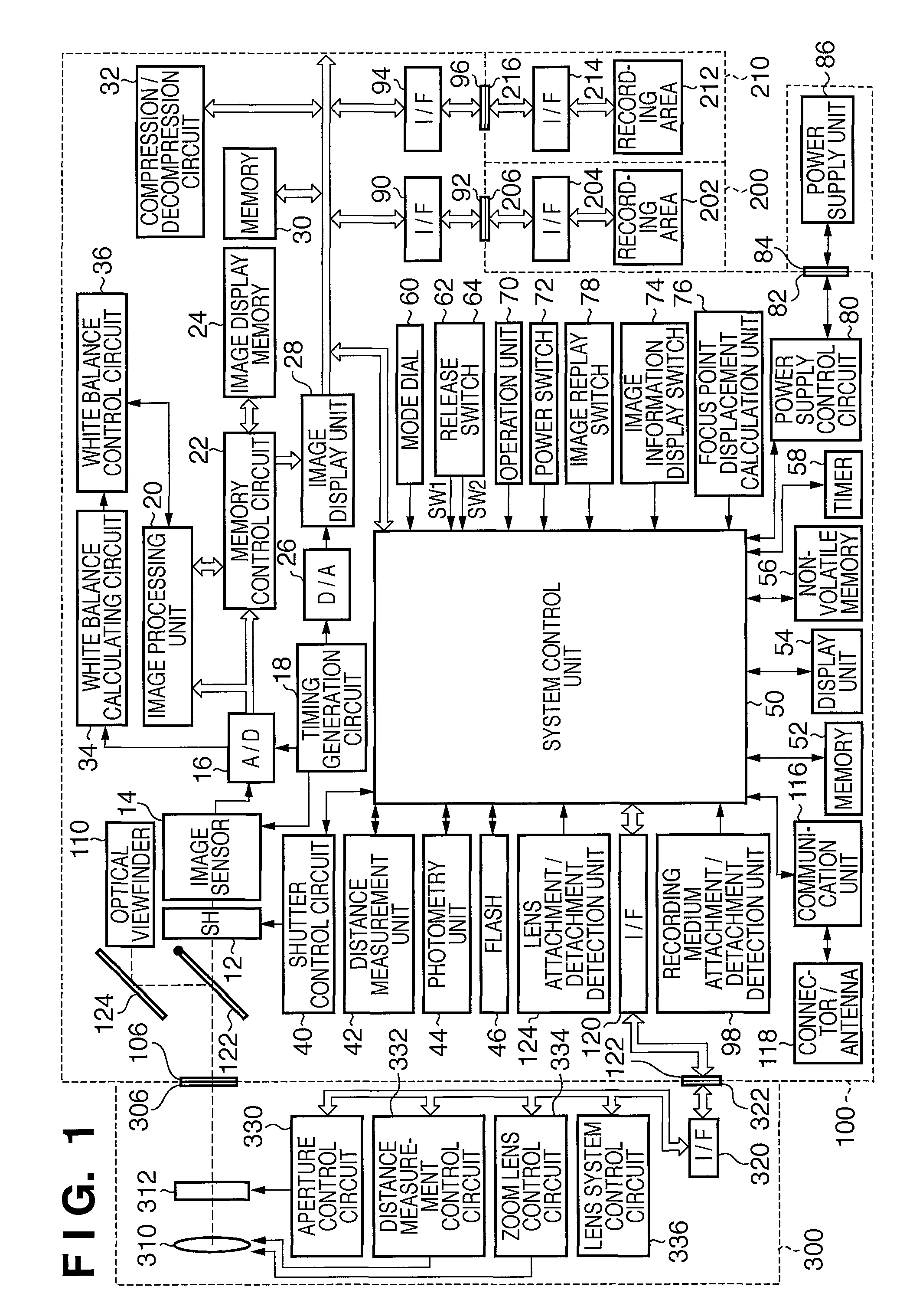
FIG. 1 is a block diagram showing the internal arrangement of a single-lens reflex digital camera common to each embodiment of the present invention.

As represented in FIG. 1, present embodiment of single-lens reflex digital camera comprises with camera body 100, photographing lens unit 300 which includes a photographing optical system comprises with multiple photographing lenses 310 and etc. Also, it comprises with media recording unit 200, 210 and power supply unit 86. The media recording unit 200, 210 and power supply unit 86 is detachable from camera body 100 accordingly.

Photographing lens unit 300 consist of activation unit which activates the photographic lens 310, aperture 312 which controls the light intensity that passes through image lens, and etc. The Photographing lens unit 300 is detachable from the camera body 100 accordingly.

Moreover, camera body comprises as follows.

12 is a shutter, which controls shutter ...

second embodiment

Second embodiment is described using FIGS. 1, 9 and 10. In current embodiment single-lens reflex digital camera internal construction is same as the first embodiment.

FIG. 9 is an internal block figure of focus point displacement calculation unit 76 which calculates the focus point displacement by comparing image data when focused and image data when shot.

162 is the first image data recording unit. When release switch SW1 (62) is turned ON, auto focus process is conducted and when focused image data is recorded.

164 is the second image data recording unit. When release switch SW2 (64) is turned ON, shot image data is recorded.

166 is main object displacement calculation unit which calculate the image data displacement using the image data from first image data recording unit 162 and the second image data recording unit 164. Image displacement calculation method such as gradient method and representative point matching exists detailed description are omitted.

FIG. 10 is a process flow ch...


PUM


Abstract

The present invention enables showing main objects position as position of focus measuring point even in case main object has moved after focusing by focus control unit, within the image screen due to framing alternation. It is an image capturing apparatus wherein image sensor conducts photo-electric conversion of object image created by photographing-lens, comprise of distance measuring unit which calculate displacement of aimed object on image sensors imaging screen, due to changes of direction of image capturing apparatus within the time interval, starting from the moment aimed object focused to photographing-lens focus point by focus control unit to the moment actual photo shooting is conducted, and recording unit which records displacement information of aimed object on imaging screen and linked image data.

Description

BACKGROUND OF THE INVENTION1. Field of the InventionThe present invention relates to a technology of recording, position of focus measuring point, with image data, on to the storage medium in such as digital cameras.2. Description of the Related ArtMany conventional cameras with ability to verify goodness / badness of object image on the spot have been proposed. However, due to space and cost restrictions, display unit such as LCD (liquid crystal display) monitor used in these cameras are limited in size. Thus, it has been quite difficult to verify goodness / badness of the object image using such display units. In addition, even though the sensed image on display unit can be zoomed to evaluate focus condition of the object image, the position of focus measuring point was unknown.Japanese Patent Laid-Open No: 2000-125178 has proposed a method to solve this problem by displaying superposition of the object image and focus detection point of the image for confirmation before recording it ...

Claims


Application Information

Patent Timeline
Patent Type & Authority Patents(United States)
IPC IPC(8): G03B13/00H04N5/76H04N5/222H04N5/225H04N5/228
CPCH04N5/23212H04N5/23293H04N5/77H04N5/772H04N5/782H04N5/907H04N9/8042H04N23/672H04N23/635
Inventor KATSUMATA, MOMOE
Owner CANON KK
Why Eureka
Try Eureka