Low power neutron generators

a neutron generator and low-power technology, applied in the field of neutron generators, can solve the problems of low power supply, chemical source disadvantage, and development of electronic neutron sources

Active Publication Date: 2011-07-12
SCHLUMBERGER TECH CORP
View PDF32 Cites 22 Cited by
  • Summary
  • Abstract
  • Description
  • Claims
  • Application Information

AI Technical Summary

Problems solved by technology

However, this is also a disadvantage of the chemical source.
This disadvantage prompted the development of electronic neutron sources.
Additionally, space applications of neutron generators for elemental surveys of planets and asteroids need systems that operate on as little power as possible.
Conventional neutron generators have rather high power requirements.

Method used


Image

  • Low power neutron generators
  • Low power neutron generators
  • Low power neutron generators

Examples


Embodiment Construction

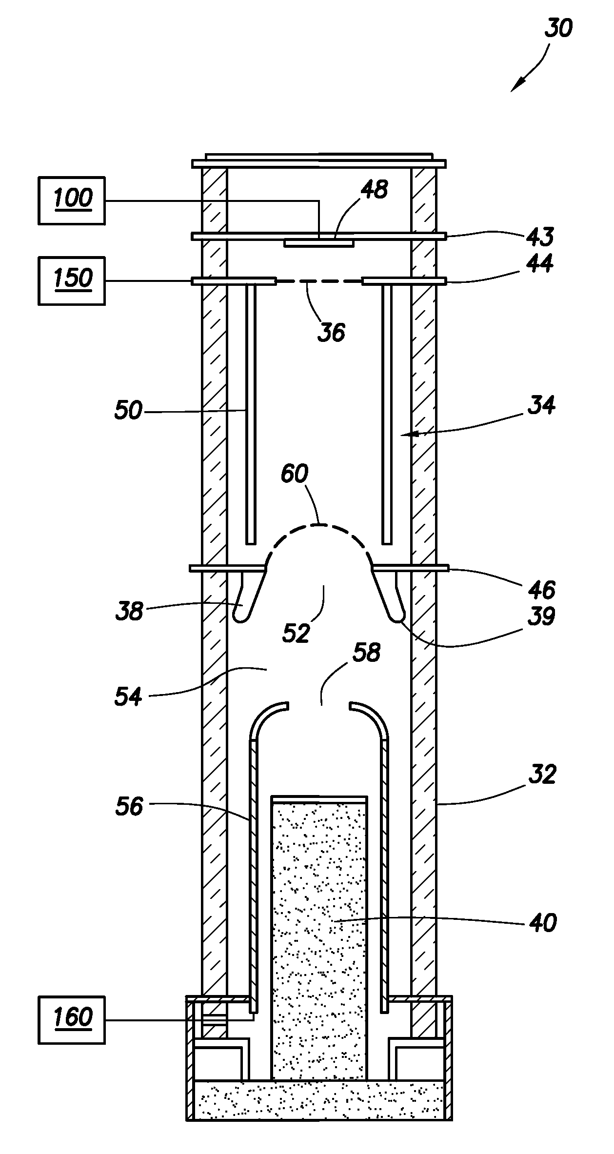
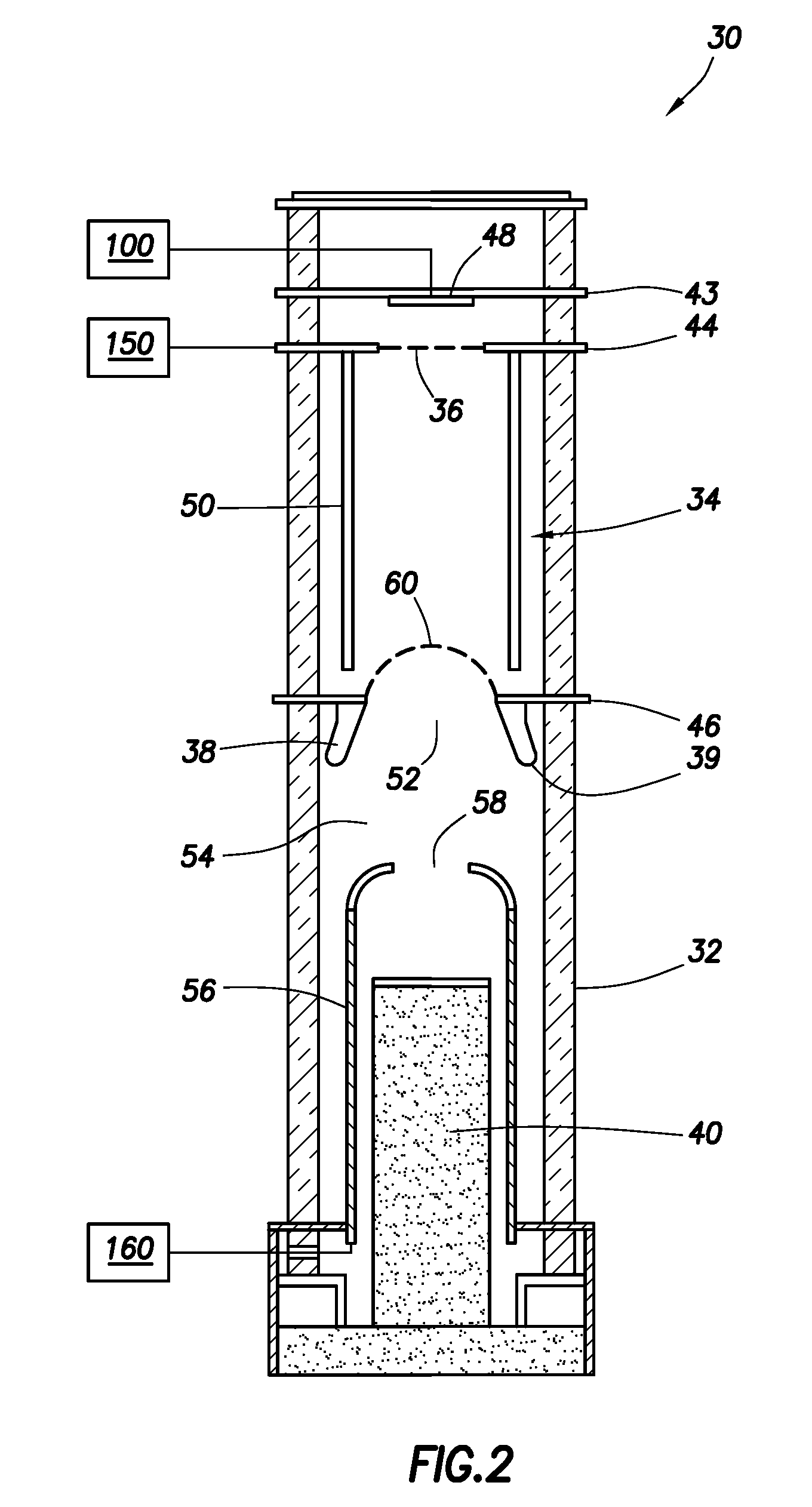
[0022]FIG. 2 shows an aspect of the invention. A neutron generator 30 generally comprising a structure similar to the generator described in U.S. Pat. No. 5,293,410 (assigned to the present assignee and entirely incorporated herein by reference) is shown. The generator 30 includes a hollow cylindrical tube 32 made of a suitable material and providing a gas-tight housing, an ion source tube 34, a gas supply grid 36, an extractor electrode 38, a target electrode 40, and a cathode 48. The tube 32 comprises parallel transversely disposed flanges 43, 44, 46 providing electrically conductive paths and sturdy support for the generator components as described herein.

[0023]The ion source tube 34 comprises a cylindrical hollow electrode 50 aligned with the longitudinal axis of the generator 30 and made out of a mesh or coil. The electrode 50 is secured rigidly to flange 44 (e.g., by conductive pads). The electrode 50 is configured to provide several functions.

[0024]A portion of the electrode ...


PUM


Abstract

A neutron generator and method of constructing the same. The generator includes a grid configured to produce an ionizable gas when heated by electrons impinging thereon. A cathode emits electrons to heat the grid and to collide with produced ionizable gas atoms to generate ions. Neutrons are generated from a collision of ions impinging on a target in the generator. A tool for subsurface use incorporating the neutron generator.

Description

BACKGROUND[0001]1. Technical Field[0002]This invention relates generally to apparatus for generating neutrons and in particular to neutron generators for subsurface applications.[0003]2. Description of Related Art[0004]The characteristics of geological formations are of significant interest in the exploration for, production and monitoring of subsurface water, oil and gas. To that end, a variety of techniques have been developed to measure subsurface characteristics and evaluate the obtained data to determine the petrophysical properties of interest. These techniques typically involve the subsurface deployment of tools or instruments equipped with sources adapted to emit energy into the formations (usually through a borehole traversing the formations). The emitted energy interacts with the surrounding formations to produce signals that are detected and measured by one or more sensors or detectors on the instrument. By processing the detected signal data, a profile or log of the subs...

Claims


Application Information

Patent Timeline
Patent Type & Authority Patents(United States)
IPC IPC(8): G21B1/00
CPCG01V5/10H05H3/06Y02E30/10
Inventor GROVES, JOEL L.PFUTZNER, HAROLD
Owner SCHLUMBERGER TECH CORP
Why Eureka
Try Eureka