Optimized video stitching method

a video and video technology, applied in the field of video stitching, can solve the problems of inability to achieve reasonable frame rate, large bandwidth requirement of external memory access for video stitching, etc., and achieve the effect of reducing the size of the memory and the access bandwidth requirement, and improving image quality

Inactive Publication Date: 2011-07-12
SONY TAIWAN
View PDF8 Cites 14 Cited by
  • Summary
  • Abstract
  • Description
  • Claims
  • Application Information

AI Technical Summary

Benefits of technology

[0006]According to another aspect of the invention, the predefined pattern images are captured by a multi-eye camera module, wherein the non-parallax points between each camera of the multi-eye camera module are aligned in a vertical direction. For stitching in horizontal direction, the alignment of the camera non-parallax points avoids the parallax problem so that the stitching points for the objects at different distance remains constant. Therefore, the operation flow of the invention can use fixed stitching points calculated from the calibration flow. There is no need to update the stitching points for each frame. Similarly, if the non-parallax points between each camera of the multi-eye camera module are aligned in a horizontal direction, the invention can be applied for stitching in a vertical direction.
[0008]In the optimized video stitching method of the invention, the combined planar and cylindrical transformation does interpolation only once. In a conventional stitching method, the interpolation is calculated twice. Therefore, the wide-angle image obtained by the invention is more precise. Only the captured video and data on the cylindrical surface are required to be stored in the DRAM. Image registration is not calculated for each frame of video data but is only processed once with the still image data during calibration. In the invention, the DRAM memory size and the access bandwidth requirement are both reduced. The method of the invention optimizes for substantial reduction in computation and the external memory access for video data. It makes the realization of the hardware video stitching engine feasible. Further, the image quality is improved compared to the conventional method because interpolation is performed only once rather than twice as compared to the conventional method.

Problems solved by technology

Therefore, the bandwidth requirement of external memory access for video stitching is very large and is not feasible with the above-mentioned method at a reasonable fps (frame per second).
Apart from this, the computation requirement for image registration puts limitation to achieve reasonable frame rate.

Method used


Image

  • Optimized video stitching method
  • Optimized video stitching method
  • Optimized video stitching method

Examples


Embodiment Construction

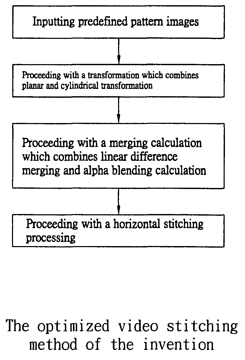
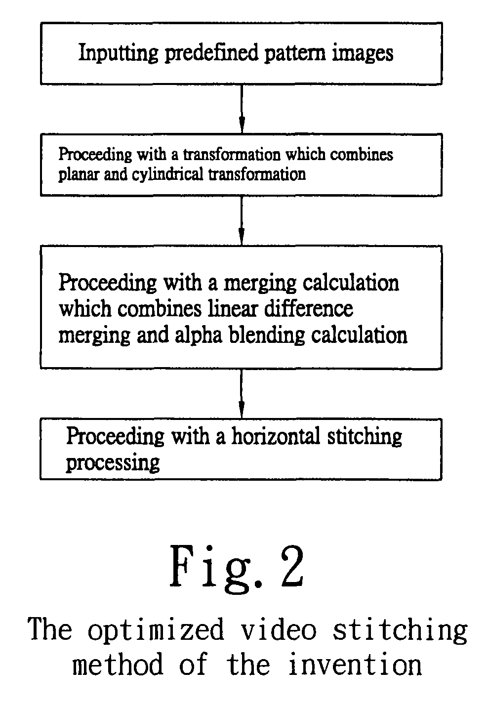
[0017]Referring to FIG. 2, the optimized video stitching method of the invention is explained. The optimized video stitching method of the invention comprises: inputting predefined pattern images; proceeding with a transformation which combines planar and cylindrical transformation; proceeding with a merging calculation which combines linear difference merging and alpha blending calculation; and proceeding with a horizontal stitching processing by putting the processed images horizontally together into one seamless wide-angle image.

[0018]In the optimized video stitching method of the invention, when a combined planar and cylindrical transformation, an image merging calculation and a horizontal stitching process are executed, a camera position calibration flow is necessary for obtaining relevant parameters. The camera position calibration flow comprises: finding a planar matrix by using predefined pattern images; proceeding with a planar transformation of image; proceeding with an im...


PUM


Abstract

The invention discloses an optimized video stitching method, comprising: inputting predefined pattern images; proceeding with a transformation which combines planar and cylindrical transformation; proceeding with a merging calculation which combines linear difference merging and alpha blending calculation; and proceeding with a horizontal stitching processing by putting the processed images horizontally together into one seamless wide-angle image. The optimized video stitching method according to the invention further comprises a camera position calibration flow comprising: finding a planar matrix by using predefined pattern images; proceeding with a planar transformation of image; proceeding with an image registration by using a block matching method to find out the stitching points on the planar surface; and proceeding with a cylindrical transformation by transforming the stitching points from the planar surface to cylindrical surface.

Description

BACKGROUND OF THE INVENTION[0001]1. Field of the Invention[0002]The invention relates to an optimized video stitching method, more especially to an optimized video stitching method for high resolution / high frame rate video.[0003]2. Description of the Prior Art[0004]A conventional stitching method, as described in the United States Patent US 20030235344A1, is shown in FIG. 1. As shown in FIG. 1, firstly, all the input images are transformed to a planar surface. Secondly, the stitching points are calculated with the image registration algorithm. Thirdly, the overlap regions of the images are merged to smooth out the differences near the stitching points and then stitched into one seamless wide-angle image. Finally, the seamless wide-angle image is transformed to a cylindrical surface. As far as the implementation in the hardware engine is concerned, the whole frame of video data needs to be stored in the DRAM on a separate chip from the stitching engine. In the conventional stitching ...

Claims


Application Information

Patent Timeline
Patent Type & Authority Patents(United States)
IPC IPC(8): G06K9/00G06K9/36G06V10/24
CPCG06K9/32G06K2009/2045G06V10/16G06V10/24
Inventor PAN, PATRICKMITSUSHITA, TATSUMILIN, CHRISTINEKUO, BENJAMIN
Owner SONY TAIWAN
Why Eureka
Try Eureka