
Device for connecting and interlocking of two base plates, especially floor panels

a technology for connecting and interlocking two base plates, applied in the direction of couplings, rod connections, manufacturing tools, etc., can solve the problems of increasing production expenditure, limiting the applicability of locking systems, and increasing costs

Active Publication Date: 2011-07-19
FLOORING TECH
View PDF12 Cites 150 Cited by
  • Summary
  • Abstract
  • Description
  • Claims
  • Application Information

AI Technical Summary

Benefits of technology

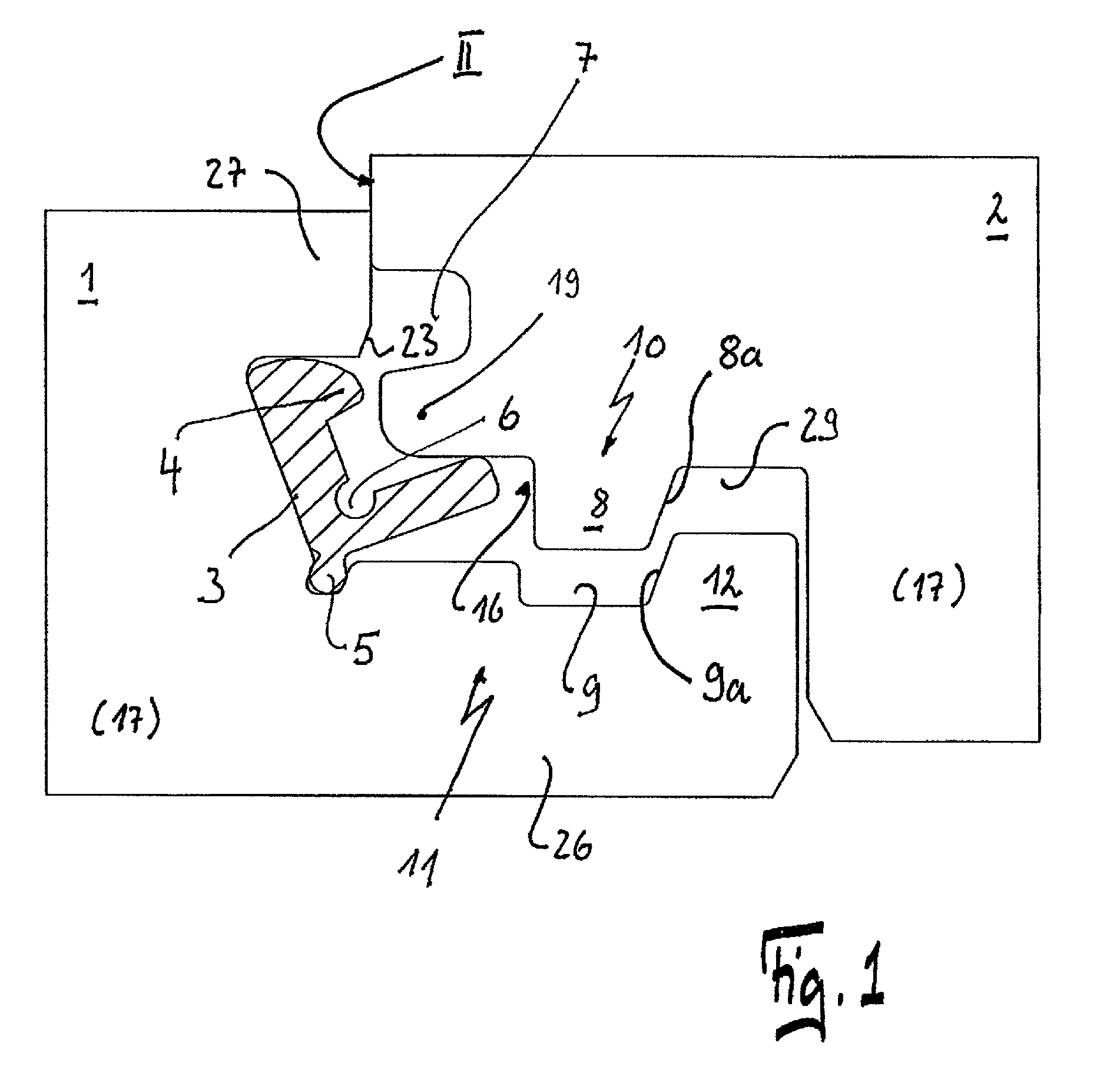
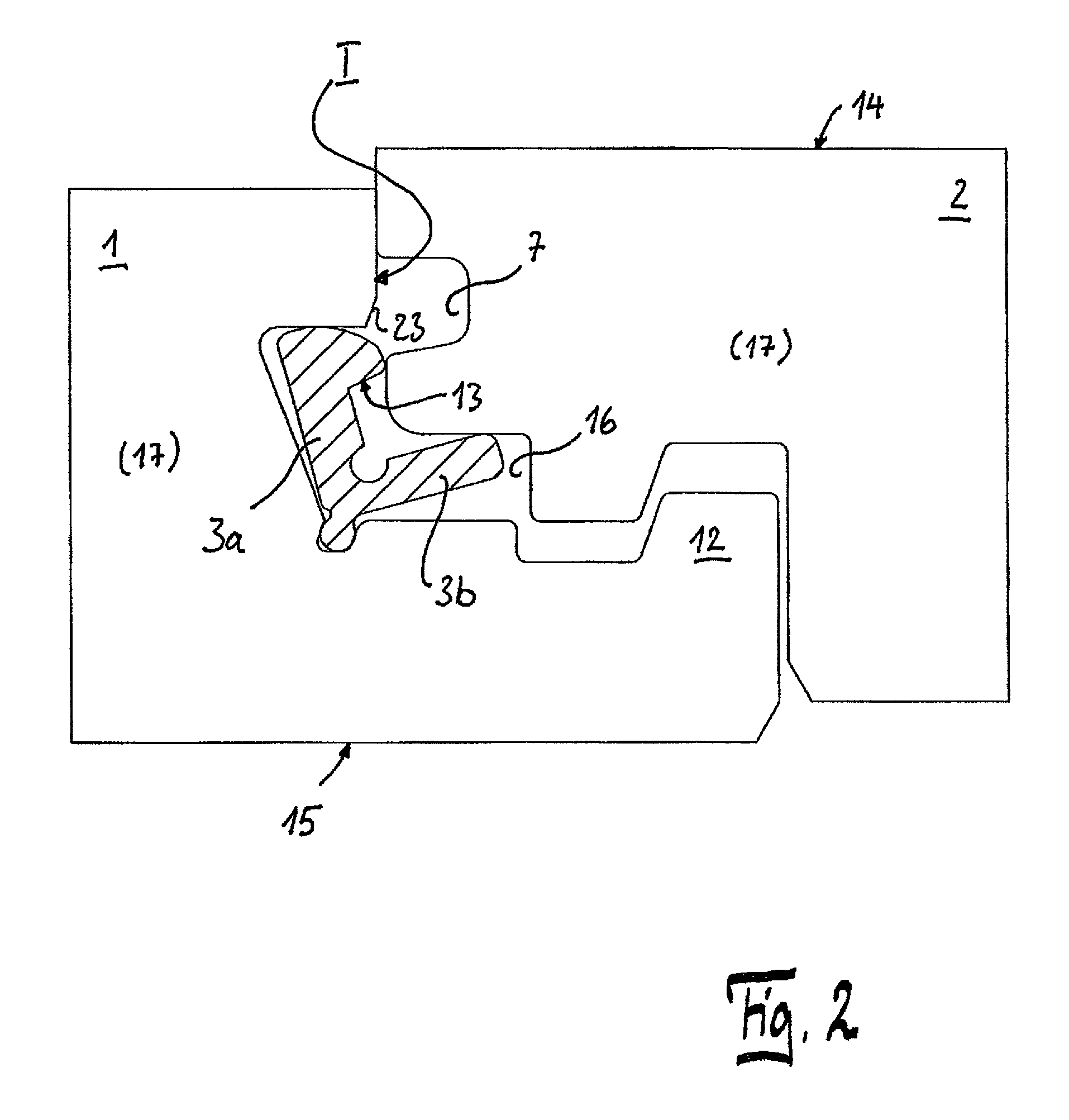
[0013]It is advantageous if the locking projection can be positively accommodated in the locking depression, and it is particularly advantageous if the locking projection and the locking depression have a locking surface, which bear against one another in the locked condition of the building boards, and then both locking surfaces run essentially parallel to the top side.

Problems solved by technology

Through the thickness of the plastic insert, the vertical locking is limited to laminate floors with thicknesses of greater than 10 mm, which further restricts the applicability of the locking system.
When a high elasticity is necessary for the locking, on the one hand the material selection is very restricted, which can lead to increased costs or to increased production expenditure.
If high forces act on a laminate, such as HDF, on small areas lengthwise to the layer direction, damage occurs very quickly, in particular in tapered areas.
Furthermore, the mostly large deformations of the locking elements often lead to a weakening, in particular when the deformation exceeds the elastic range or the deformation lasts for a longer period.
This can lead to reduced restoring forces of the locking elements and thus to only incomplete locking.

Method used


Image

  • Device for connecting and interlocking of two base plates, especially floor panels
  • Device for connecting and interlocking of two base plates, especially floor panels
  • Device for connecting and interlocking of two base plates, especially floor panels

Examples


Embodiment Construction

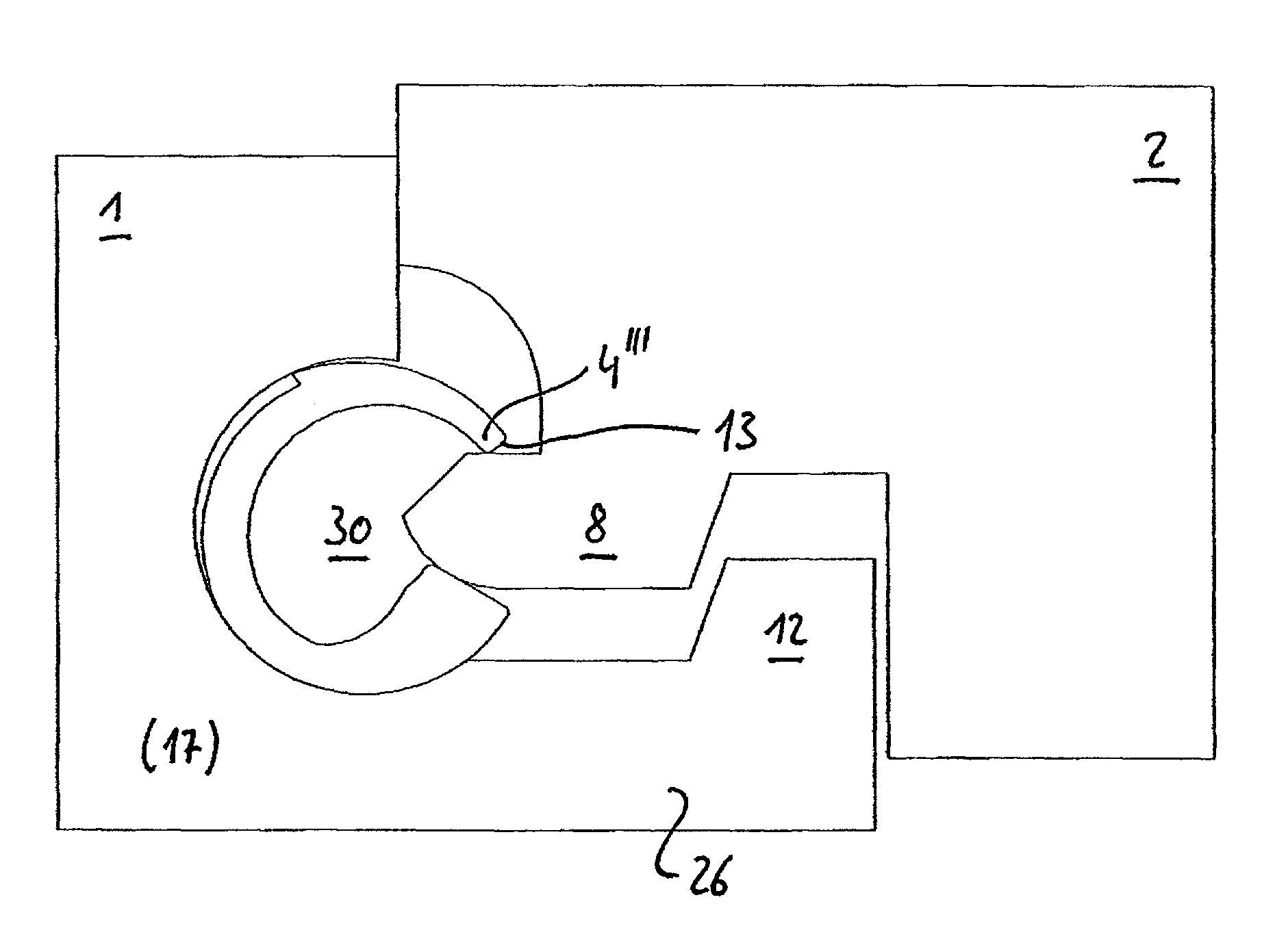
[0049]The invention is to be explained for floor panels that can be connected to one another via the device according to the invention at their longitudinal sides as well as at their transverse sides or else at only one side. The device is provided to connect panels on their transverse sides. The longitudinal sides are preferably connected by angling a new panel into a panel already lying on the floor and subsequent lowering onto the subfloor. The joining movement on the transverse side then takes place essentially in the vertical direction.

[0050]As can be seen from the drawing, the panels 1, 2 are provided on their lateral edges I, II with hook-shaped profiles 10,11 corresponding to one another. Even though a first and a second panel is spoken of here, each panel 1, 2 is of course profiled identically and the profiles 10, 11 correspond to one another. The panel 1 is profiled starting from its top side 14 and the panel 2 is profiled starting from its underside 15. The profiles 10, 1...


PUM


Abstract

A device for connecting and locking two building boards, in particular floor panels, on their longitudinal sides and / or transverse sides in the horizontal and vertical direction through an essentially vertical joining movement. The building boards have a top side and an underside. On their lateral edges to be connected to one another are provided with profiles corresponding to one another. A locking element with a locking projection is provided in the profile of the first building board. The locking projection interacts with a locking depression provided in the profile of the second building board such that the two building boards are automatically locked in the vertical direction with the joining movement. The locking element is embodied in an essentially rigid manner and the locking projection can be brought into the locking depression through a rotary motion of the locking element.

Description

CROSS REFERENCE TO RELATED APPLICATIONS[0001]This present application claims priority under 35 U.S.C. §119 to German Patent Application No. 10 2007 042 250.6, filed on Sep. 6, 2007, the contents of which are incorporated in their entirety herein by reference.BACKGROUND OF THE INVENTION[0002]1. Field of the Invention[0003]The invention relates to a device for connecting and locking two building boards, in particular floor panels, on their longitudinal sides and / or transverse sides in the horizontal and vertical direction through an essentially vertical joining movement, wherein the building boards have a top side and an underside, on their lateral edges to be connected to one another are provided with profiles corresponding to one another, and a locking element with a locking projection is provided in the profile of the first building board, which locking projection interacts with a locking depression provided in the profile of the second building board such that the two building boa...

Claims


Application Information

Patent Timeline
IPC IPC(8): E04B5/00E04C2/38
CPCE04F15/02F16B5/0056E04F2201/0138E04F2201/0176Y10T403/7009E04F2201/0547E04F2201/0552E04F2201/0523
Inventor GROEKE, CARSTENGRAFENAUER, THOMAS
Owner FLOORING TECH
Learn More