Projection display device

a technology of projection display and projection device, which is applied in the direction of projection device, television system, picture reproducer, etc., can solve the problem of difficult to precisely grade the safety level of lasers, and achieve the effect of less expensiv

Inactive Publication Date: 2005-09-20
CANON KK
View PDF16 Cites 142 Cited by
  • Summary
  • Abstract
  • Description
  • Claims
  • Application Information

AI Technical Summary

Benefits of technology

[0012]It is an object of the present invention to provide a small, less expensive projection display which forms a high-resolution projection image free from image unevenness by scanning light beams.
[0018]In the projection display device, the plural light beams are combined on a single light path by a color combining element such as an optical wavelength filter, a color separation prism, or a diffraction grating. Also, the plural light beans include pulses of red, green, and blue light which are emitted synchronously. With this configuration, the projection display device displays an image having precise color reproduction and high-resolution.
[0019]In the projection display device, the plural light beams are incident on at least one of the light scanning elements at different angles and then are scanned. Alternatively, the plural light beams are incident at different points on at least one of the light scanning elements and are scanned. With any of these configurations, the projection display device has a reduced number of parts, a small size, and a low price. Also, since the pulses of light corresponding to a display pixel are projected in a time-shifting manner from color to color, the light beams can be reliably dealt as a string of pulsed light and the wavelengths can be considered separately, thereby allowing the laser safety standards to be applied to the projection display device further precisely.
[0020]In the projection display device, at least one of the light sources for emitting the light beams is an edge emitting laser. Alternatively, at least one of the light sources for emitting the light beams is a super-luminescent diode, a surface emitting laser, a light emitting diode, a resonant-type light emitting diode, or a laser diode pumped solid-state laser. In another alternative, at least one of the light sources for emitting the light beams emits the second harmonic of laser light as a light beam. With any of these configurations, the projection display device has a small size by making the light source smaller. In addition, the light source operates with low electrical power and generates less heat because of high electricity-light conversion efficiency of the light source, resulting on either no structure or a simple structure being needed for heat radiation.

Problems solved by technology

When the light beams can not be defined as pulsed light kept in a certain period of duration, it is difficult to precisely grade a laser safety level depending on conditions, since a time in which the light beams intersect an aperture of a measuring probe for scanning is not fixed when measuring laser radiation.

Method used


Image

  • Projection display device
  • Projection display device
  • Projection display device

Examples


first embodiment

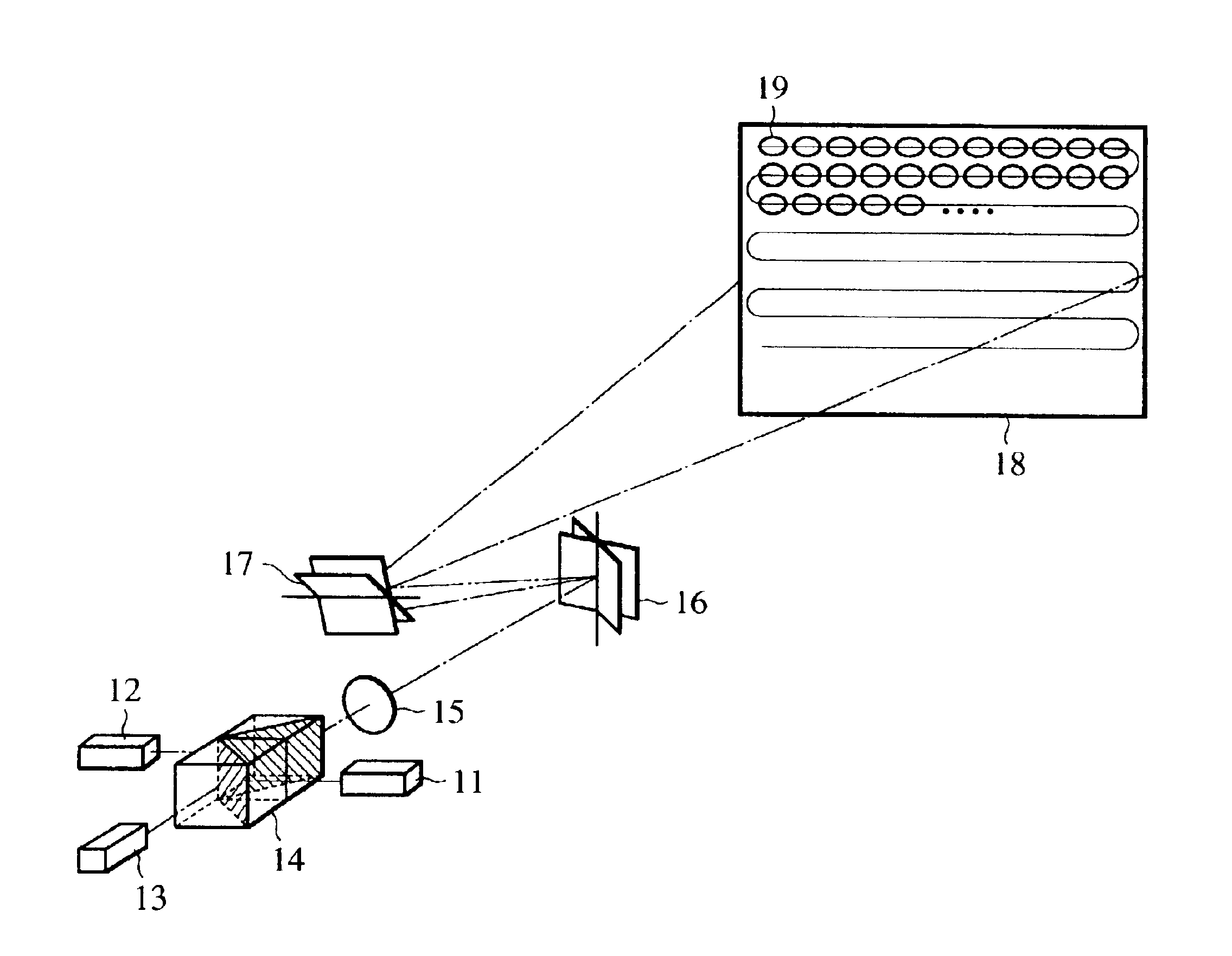
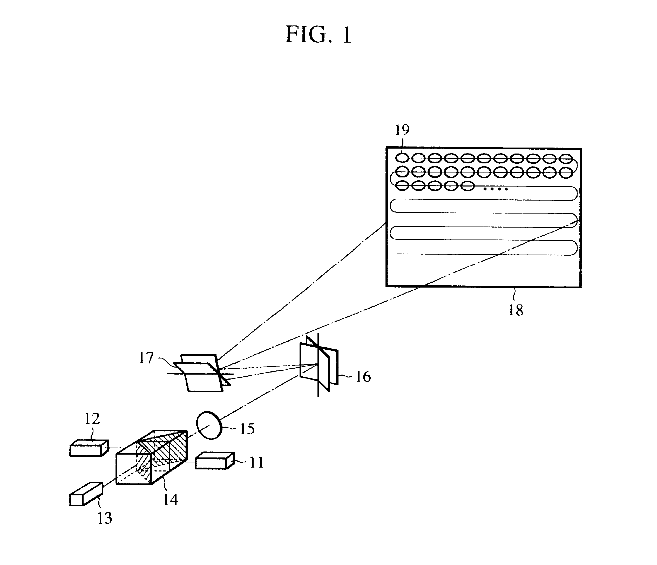
[0035]FIG. 1 illustrates the configuration of a projection display device according to a first embodiment of the present invention, wherein reference numerals 11, 12, and 13 denote a light source formed of a red semiconductor laser, a light source formed of a blue semiconductor laser, and a light source formed of an infrared laser diode pumped green solid-state laser (hereinafter, laser diode is referred to as LD), respectively, reference numerals 14, 15, and 16 denote a color combining element having multiple beam interference films formed therein, a collimator lens, and a micromechanical mirror comprising a silicon substrate, respectively, and reference numerals 17, 18, and 19 denote a mechanical galvanometer mirror driven by a stepping motor, a projection plane, and pixels displayed by laser projection, respectively.

[0036]The semiconductor laser 11 is a red light source formed from the compound of InGaAlP having a central wavelength of 635 nm and the semiconductor laser 12 is a b...

second embodiment

[0046]Another projection display device according to a second embodiment of the present invention will be described with reference to FIG. 5. Unlike the first embodiment, the projection display device according to the second embodiment uses, as light sources, super-luminescent diodes having a lower coherency than that of a laser. Each laser feedback of a red light source 51a and a blue light source 51b is suppressed by skewing the end face of the resonator of the corresponding semiconductor laser relative to an axis of a waveguide of the laser or by applying an anti-reflection film on the end face. This configuration allows the oscillating light to have a larger spectral line width and a lower spatial coherency. Although the directivity of the light beam becomes lower than that of the laser, this directivity does not cause a problem when performing display by projection according to the present invention. The projection display device has an advantage in that the risk of glare cause...

third embodiment

[0050]Another projection display device according to a third embodiment of the present invention will be described with reference to FIG. 6. In the third embodiment, light beams from a red light source 61, a green light source 62, and a blue light source 63 are incident on light scanning elements 65 and 66 without combining these beams with a color combining element. More particularly, as shown in the drawing, the three light beams are incident on the horizontal scanning element 65 at different angles, are reflected at the vertical scanning element 66, and then form an image on a projection plane 67. A collimator 64 can be disposed either in front of or behind the light scanning elements 65 and 66 in the drawing. The optimal arrangement of the collimator optical system 64 is set considering the distance to the projection plane, the image resolution, the size of the projection display device, and so forth. The light scanning element 65 is a micromechanical mirror comprising a silicon...


PUM


Abstract

Light beams having different wavelengths emitted from red and blue semiconductor lasers and a laser diode pumped green solid-state laser are incident on respectively different surfaces of a color combining element and are overlaid on a single light path. Multiple beam interference films of the color combining element allow only the light beams having the oscillating wavelengths corresponding to the respective light sources to pass therethrough or reflect thereon so as to combine the light beams. A collimator collimates the light beams so that the beam waist of the light beams lies around a projection plane. When two-dimensional scanning is performed by radiating the light beams onto a micromechanical mirror and then onto a galvanometer mirror for scanning light in the horizontal and vertical directions, respectively, a color image is displayed on the projection plane by arranging pixels in array, each pixel consisting of overlapping pulses of light of three colors.

Description

BACKGROUND OF THE INVENTION[0001]1. Field of the Invention[0002]The present invention relates to projection display devices, and more particularly, to a projection display device which projects a still image or a moving image, which is formed on a screen such as a computer screen or a TV screen, onto a projection plane such as a screen or a wall by scanning light beams.[0003]2. Description of the Related Art[0004]Hitherto, so-called projection laser displays which scan and project laser beams of three colors, that is, red, green, and blue, have been widely available, and an exemplary projection laser display is described in Electronics and Communications in Japan, Vol. 68, No. 4, pp. 387-394. In this example, red, green, and blue laser beams are amplitude modulated by an optical modulator and are combined on a single optical axis, and then an image is projected onto a screen by scanning the combined beams two-dimensionally with horizontal and vertical optical scanning elements. Alth...

Claims


Application Information

Patent Timeline
Patent Type & Authority Patents(United States)
IPC IPC(8): H04N9/31G02B26/10G02B27/18H04N5/74
CPCG03B21/2033H04N9/3129
Inventor SAKATA, HAJIMEFURUKAWA, YUKIO
Owner CANON KK
Why Eureka
Try Eureka