
Ophthalmic photographing apparatus

Active Publication Date: 2011-07-19
NIDEK CO LTD
View PDF5 Cites 53 Cited by
  • Summary
  • Abstract
  • Description
  • Claims
  • Application Information

AI Technical Summary

Benefits of technology

The present invention provides an ophthalmic photographing apparatus that can obtain tomographic images of both the fundus and the anterior segment of the eye. The apparatus includes an interference optical system, a first driving part, an image obtaining part, and a driving control unit. The first driving part moves an optical member in one of the measurement optical path and the reference optical path to adjust the optical-path difference between the two paths. The image obtaining part obtains a tomographic image of the fundus in a fundus photographing mode and a tomographic image of the anterior segment in an anterior segment photographing mode based on the light receiving signal output from the detector. The driving control unit controls the driving of the first driving part in the case of the fundus photographing mode and the driving of the first driving part to locate the optical member in a predetermined position corresponding to the anterior segment photographing mode in the case of the anterior segment photographing mode. The technical effect of the invention is that it can favorably photograph the anterior-segment tomographic image.

Problems solved by technology

However, there have been possibilities that a tomographic image in a state out of focus is obtained, or the lens system of the adaptor is erroneously obtained as a tomographic image.

Method used


Image

  • Ophthalmic photographing apparatus
  • Ophthalmic photographing apparatus
  • Ophthalmic photographing apparatus

Examples


Embodiment Construction

[0031]Preferred embodiments of the present invention will be described below with reference to the accompanying drawings, in which like reference characters designate similar or identical parts throughout the several views thereof.

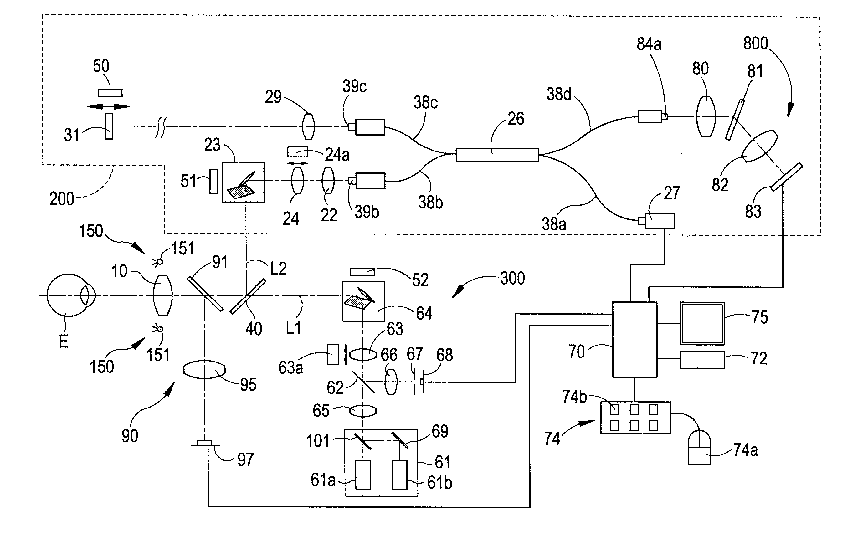
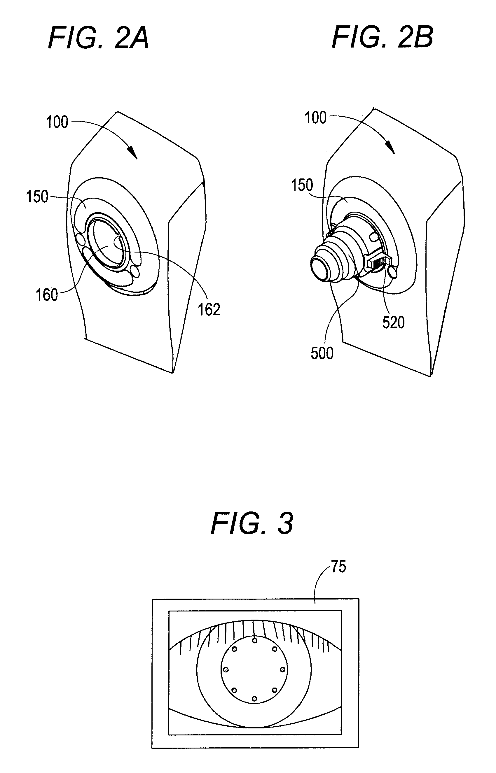
[0032]An embodiment in accordance with an aspect of the present invention will be described based on the drawings. FIG. 1 is a view showing an optical system and a control system in an ophthalmic photographing apparatus of the present embodiment. It is to be noted that in the present embodiment, a description is given with a depth direction of an examinee's eye referred to as a Z-direction (direction of optical axis L1), a horizontal direction referred to as an X-direction, and a vertical direction referred to as a Y-direction.

[0033]As shown in FIG. 1, the optical system of this ophthalmic photographing apparatus is broadly divided into an interference optical system (hereinafter referred to as OCT optical system) 200 and a scanning laser ophthalmoscope (S...


PUM


Abstract

An ophthalmic photographing apparatus includes: an interference optical system including a splitter that splits light, emitted from a measurement light source, into measurement light and reference light, and synthesizing the measurement light reflected on an eye with the reference light to guide the synthesized light to a detector; a driving part that moves an optical member arranged in the optical path to adjust an optical-path difference between the measurement light and the reference light; an image obtaining part that obtains a tomographic image of a fundus or an anterior segment based on a light receiving signal output from the detector; and a driving control unit that controls driving of the driving part to locate the optical member in a predetermined position corresponding to either a photographing mode for photographing the tomographic image of the fundus or a photographing mode for photographing the tomographic image of the anterior segment.

Description

CROSS-REFERENCE TO RELATED APPLICATION[0001]This application is based on Japanese Patent Applications No. 2010-011355 and No. 2010-011366 filed with the Japan Patent Office on Jan. 21, 2010, the entire content of which is hereby incorporated by reference.BACKGROUND[0002]1. Technical Field[0003]An aspect of the present invention relates to an ophthalmic photographing apparatus for photographing a tomographic image of an examinee's eye.[0004]2. Related Art[0005]There is known an ophthalmic photographing apparatus (Optical Coherence Tomography: OCT) which has an interference optical system and photographs a tomographic image of a fundus. The interference optical system of this apparatus splits light emitted from a light source into measurement light and reference light. This interference optical system then guides the measurement light to a predetermined region of an examinee's eye, while guiding the reference light to a reference optical system. Subsequently, the interference optical ...

Claims


Application Information

Patent Timeline
Patent Type & Authority Patents(United States)
IPC IPC(8): A61B3/14A61B3/10
CPCA61B3/102A61B3/1025A61B5/0073A61B5/0066
Inventor TAKI, SEIJIABE, YUKIONAKANISHI, HIROYOSHIMURATA, TOSHIOFURUUCHI, YASUHIRO
Owner NIDEK CO LTD
Learn More