Implant equipped for nerve location and method of use

a nerve location and implant technology, applied in the field of surgical implants, can solve the problems of implant that is dangerously close to or impinging on a neural structure, the muscle response may be attenuated to a point where the muscle response is not perceptible, and the nerve damage may be still present, so as to avoid any neural structure

Active Publication Date: 2011-07-19
NUVASIVE
View PDF19 Cites 68 Cited by
  • Summary
  • Abstract
  • Description
  • Claims
  • Application Information

AI Technical Summary

Benefits of technology

[0012]The purpose of this invention is to provide an implant suitable for neurophysiological monitoring of a target implant site. The implant includes a body member having a proximal and distal end, wherein the distal end is constructed and arranged to secure to a surgical target site. The distal end includes at least one region constructed and arranged to emit an electrical potential in an amount effective to generate a stimulating electrical signal in any proximally located neural structure. The stimulating electrical signal provides the distance and / or direction of the neural structure relative to the distal end during securement of the implant in vivo. Thus, the implant may be maneuvered during surgery such that any neural structure may be avoided.
[0013]Accordingly, it is an objective of the instant invention to provide an implant constructed and arranged for securement to a surgical target area whereby any neural structures located proximate to or at the target area may be avoided.
[0014]Another objective of the instant invention to provide a system that minimizes neural damage, thereby providing less post-operative pain.
[0016]Still a further objective of the invention is to teach an implant which allows for shorter surgery, decreased x-ray exposure, and fewer complications for the patient.

Problems solved by technology

This requires that the surgeon continuously observe the muscular response; however, when anaesthesia is used the muscular response may be attenuated to a point where the muscular response isn't perceivable by the surgeon.
Thus, the surgeon using this device may still damage the nerve.
This can create in a proximity gap between the installation equipment and the implant tip which could result in an implant that is dangerously close to or impinging a neural structure.
This system also provides a proximity gap between the location of the anode(s) on the accessories and the implant, which could result in an implant residing dangerously close to or impinging a neural structure.

Method used


Image

  • Implant equipped for nerve location and method of use
  • Implant equipped for nerve location and method of use
  • Implant equipped for nerve location and method of use

Examples


Embodiment Construction

[0022]For the purposes of promoting an understanding of the principles of the invention, reference will now be made to the embodiments illustrated in the drawings and specific language will be used to describe the same. However, the illustrated embodiments are merely exemplary. It is understood that no limitation of the scope of the invention is thereby intended. Any alterations and further modifications in the illustrated devices, and such further application of the principles of the invention as illustrated herein are contemplated as would normally occur to one skilled in the art to which the invention relates.

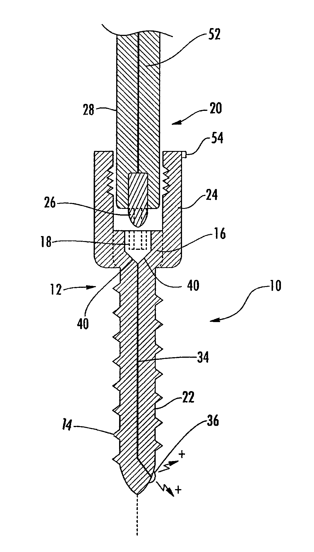
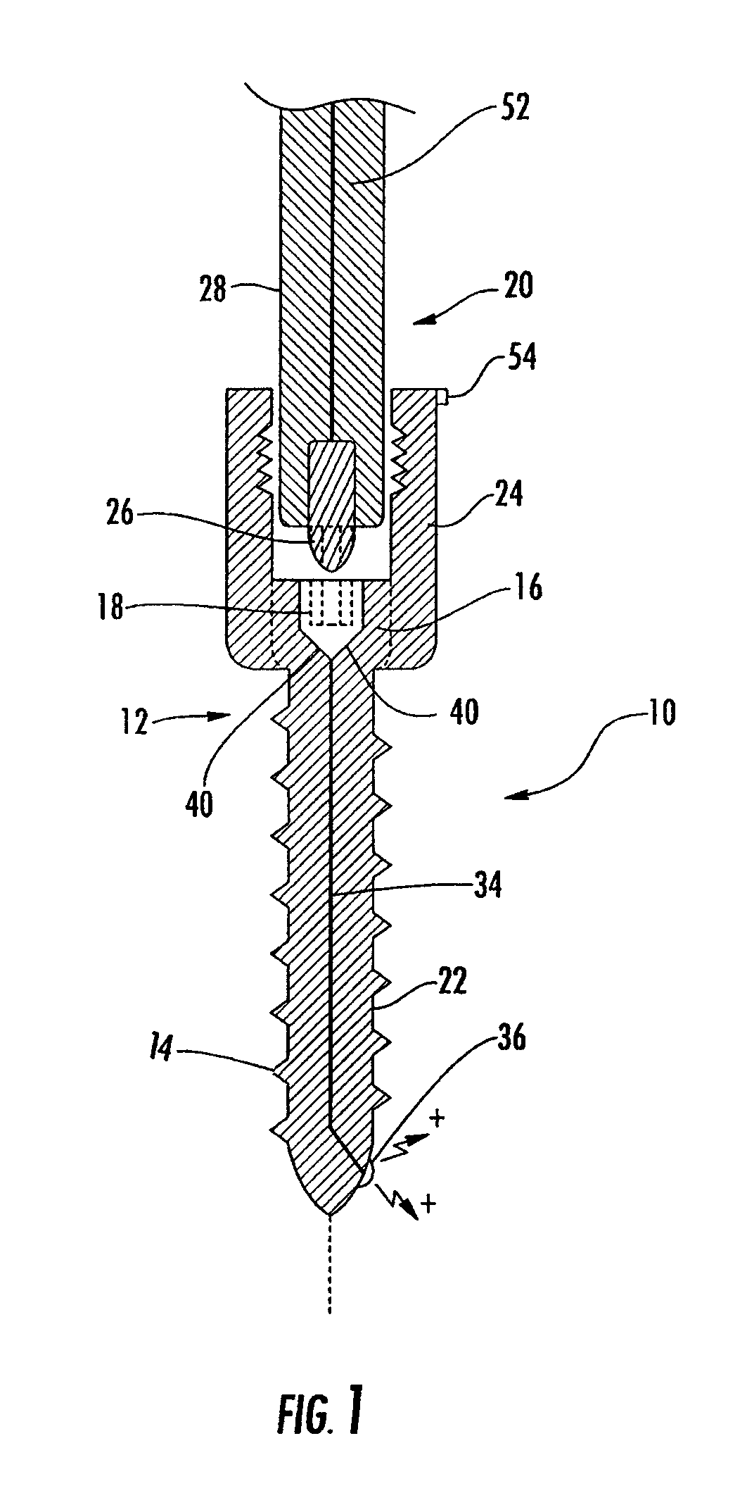
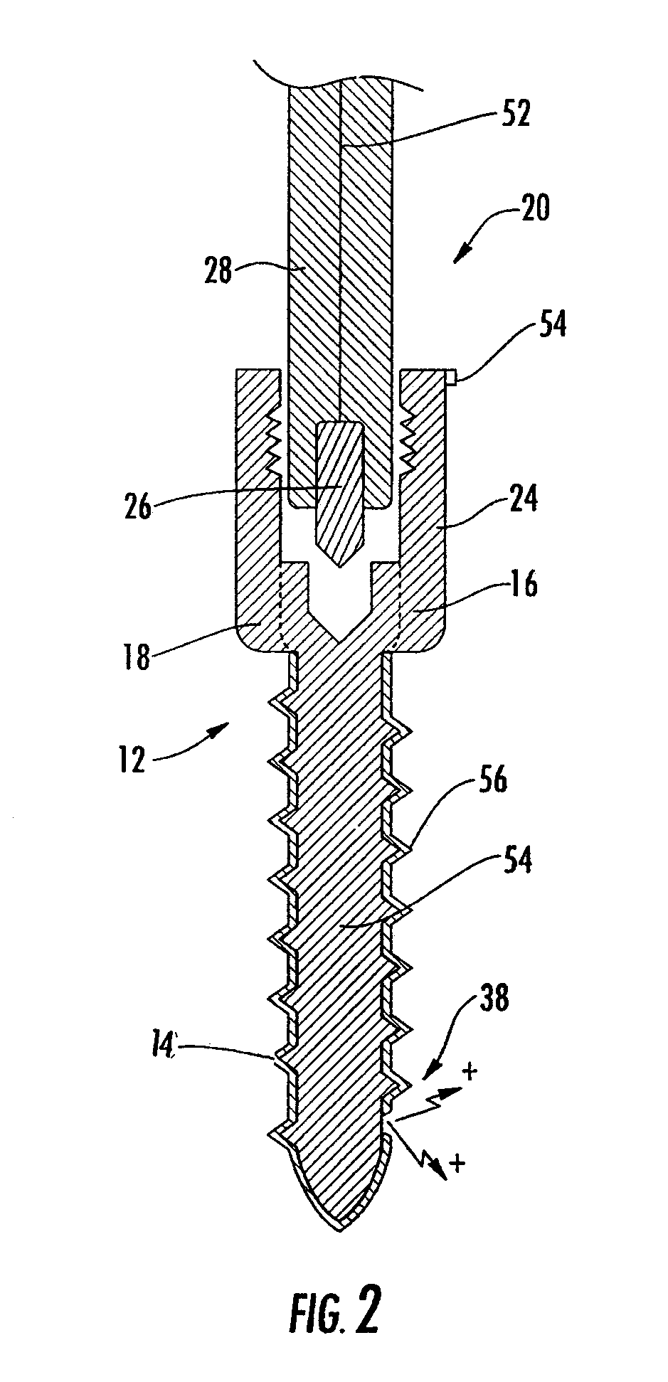
[0023]Referring now to FIGS. 1-3 which illustrate the implant 10 of the present invention suitable for neurophysiological monitoring of a target site, wherein like elements are numbered consistently throughout. FIG. 1 shows one non-limiting example of an implant, depicted here as fixed-axial pedicle or bone screw. The bone fastener body includes a proximal end 12 and a dista...


PUM


Abstract

The invention describes a surgical implant that is equipped to provide neurological data during and after implantation. Neurological monitoring ensures accurate insertion of the implant with minimal disturbance of neural structures. The implant includes at least one electrically conductive region that is utilized to determine the distance from and direction to a nerve with respect to the implant.

Description

FIELD OF THE INVENTION[0001]The invention generally relates to surgical implants and methods for their insertion; particularly to surgical implants and methods using an electrical potential to avoid nerve damage during surgical insertion of implants; most particularly to an implant having at least one electrically conductive region that is utilized to determine the distance from and direction to a nerve with respect to the implant.BACKGROUND OF THE INVENTION[0002]Pedicle screw fixation has become the favored mode of rigid internal fixation of the three vertebral columns of the spine. The use of pedicle screw-based instrumentation systems has steadily increased over the past three decades due to their superior biomechanical properties and higher bony fusion rates. However, violation of the pedicle medial wall or vertebral body while implanting these screws carries the risk of injury to neural, vascular, and visceral structures. For example, the screw body can break through the verteb...

Claims


Application Information

Patent Timeline
Patent Type & Authority Patents(United States)
IPC IPC(8): A61B17/04A61B17/84A61F2/08
CPCA61B5/0492A61B5/4893A61B5/6846A61B17/8625A61B17/8875A61B2017/00039A61B5/296
Inventor GEIST, WYATT DRAKEWALSH, CHRISTOPHER
Owner NUVASIVE
Why Eureka
Try Eureka