Broadcast receiver

a receiver and broadcast technology, applied in the field of broadcast receivers, can solve the problems of not being able unable to specify an appropriate audio output threshold for recognizing highlight scenes, and unable to devote himself or herself to enjoying the program shown in the main pictur

Inactive Publication Date: 2011-07-19
MITSUBISHI ELECTRIC CORP
View PDF12 Cites 8 Cited by
  • Summary
  • Abstract
  • Description
  • Claims
  • Application Information

AI Technical Summary

Benefits of technology

[0010]It is an object of the present invention to provide a broadcast receiver that can detect a specified scene of a television broadcast appropriately, independently of the sound system, and can make a notification or perform control in accordance with the appropriately detected scene.

Problems solved by technology

With this type of use, however, the viewer must watch the main-picture while paying attention to the sub-picture without sound output and cannot devote himself or herself to enjoying the program shown in the main-picture.
The viewer may miss a highlight scene broadcasted in the sub-picture when the viewer fails to notice the highlight scene.
It is, however, hard to specify an appropriate audio output threshold for recognizing a highlight scene, on the basis of the audio output level that depends largely on the broadcast station and program.
If the viewer does not want the automatic picture changeover, that is, if the viewer's interest has turned from the program before the change of the channel in which the end of a CM break has been monitored to the currently viewed program after the channel change, the viewer would find the automatic picture changeover embarrassing.

Method used


Image

  • Broadcast receiver
  • Broadcast receiver
  • Broadcast receiver

Examples


first embodiment

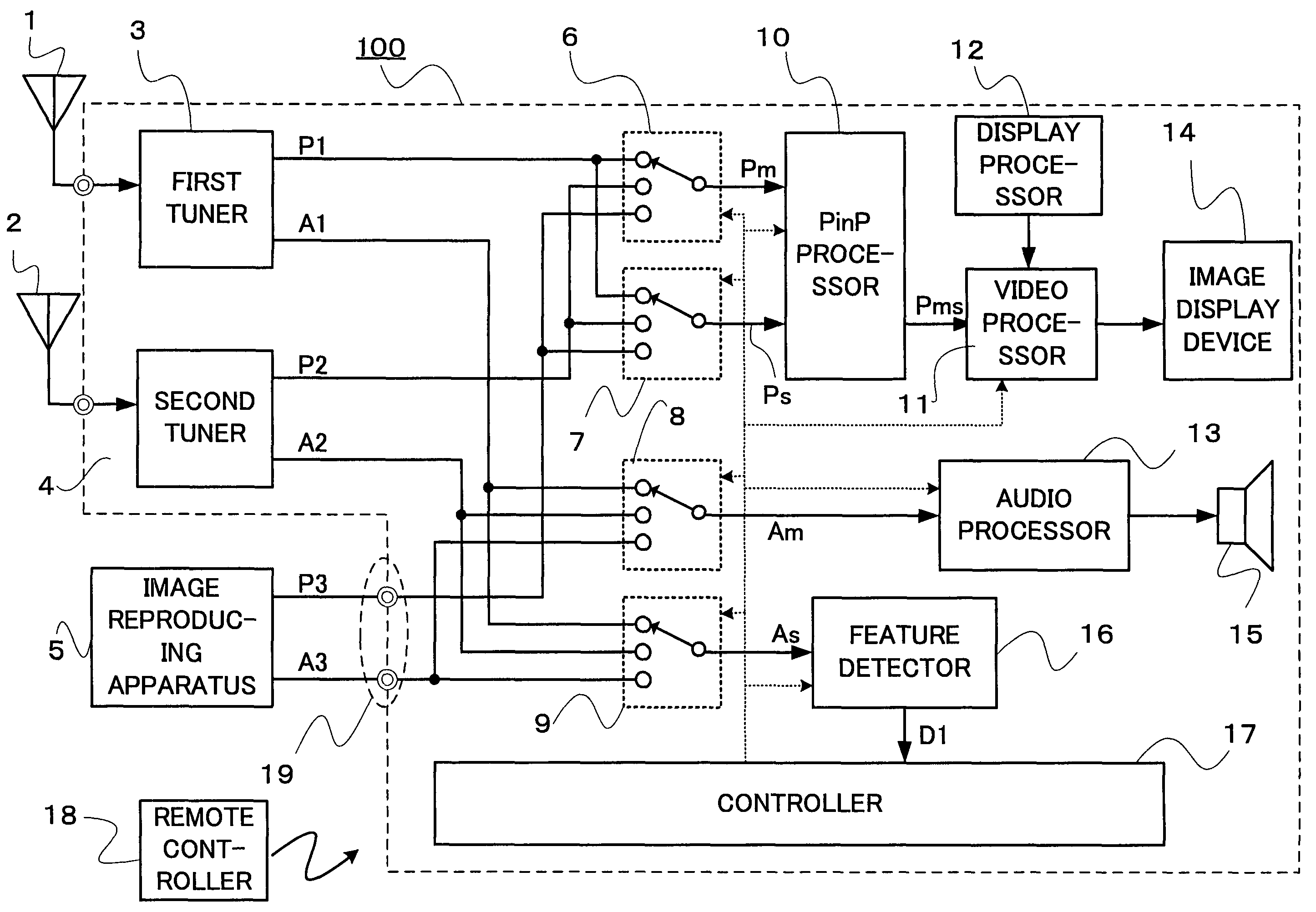
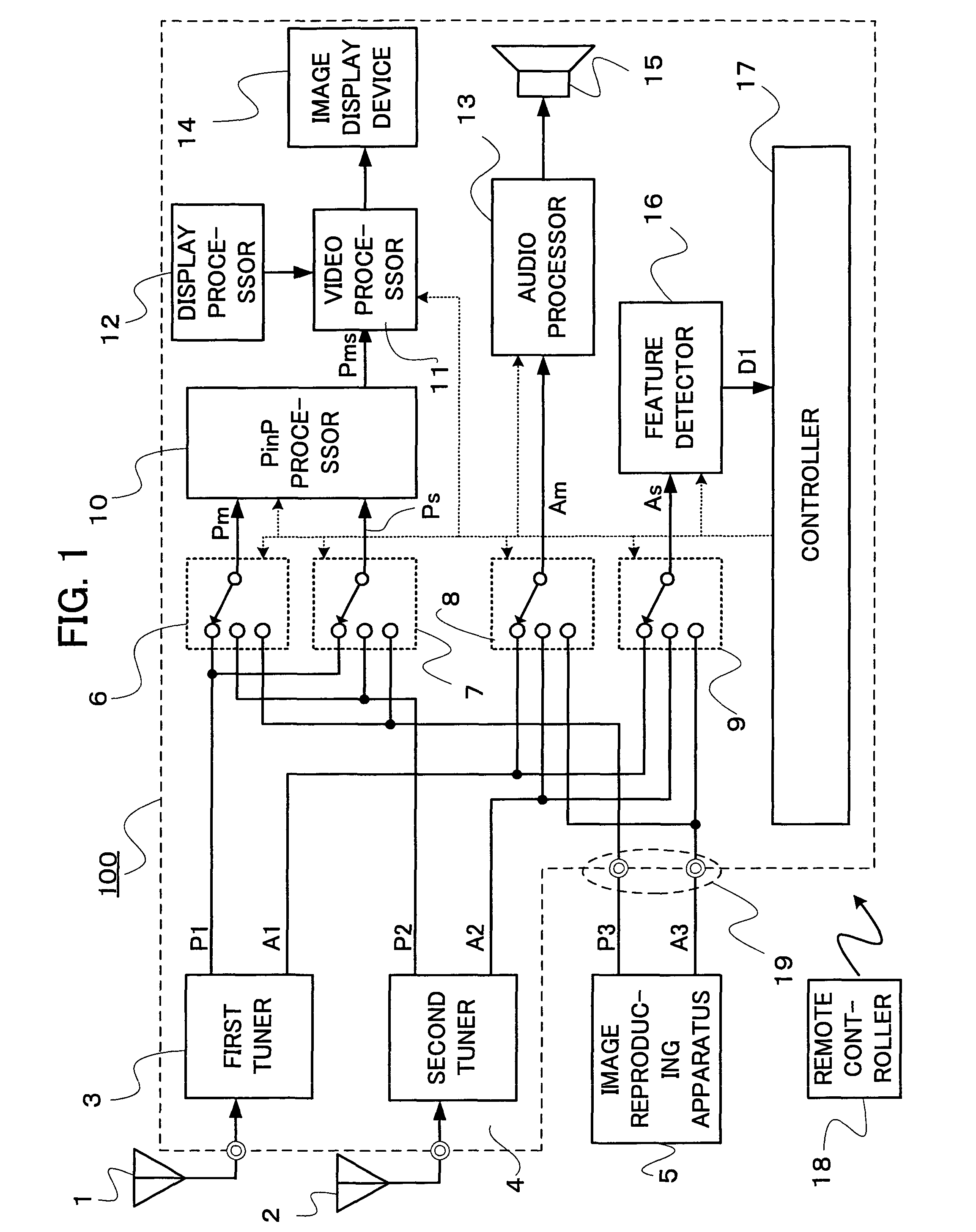
[0025]FIG. 1 is a block diagram showing a configuration of a broadcast receiver such as a television receiver 100 according to the first embodiment of the present invention.

[0026]As shown in FIG. 1, the television receiver 100 includes a first tuner 3, to which a first antenna 1 is connected; and a second tuner 4, to which a second antenna 2 is connected. The television receiver 100 also includes a video signal selector 6 which receives video signals P1, P2 and P3, and selects one of them to output a video signal Pm of the main-picture; a video signal selector 7 which receives the video signals P1, P2 and P3, and selects one of them to output a video signal Ps of the sub-picture; an audio signal selector 8 which receives audio signals A1, A2 and A3, and selects one of them to output an audio signal Am of the main-picture, synchronized with the video signal Pm of the main-picture; and an audio signal selector 9 which receives the audio signals A1, A2 and A3, and selects one of them t...

second embodiment

[0066]FIG. 7 is a flow chart showing threshold change processing in a broadcast receiver such as a television receiver according to the second embodiment of the present invention. Steps S70 to S74 shown in FIG. 7 are performed by the controller 17. The television receiver according to the second embodiment is the same as the television receiver according to the first embodiment, except for the processing of the controller 17.

[0067]The threshold change processing by the controller 17 will be described in further detail with reference to FIG. 7. When a report of the detection of a highlight scene is received from the feature detector 16, the controller 17 automatically switches the pictures and sound of the main-picture and the sub-picture (step S70). The picture that had been selected for the sub-picture by the video signal selector 7 is selected by the video signal selector 6 and displayed as the main-picture by the image display device 14, and the audio signal accompanying the pict...

third embodiment

[0072]In the first embodiment, when a report of the detection of a highlight scene is received from the feature detector 16, the controller 17 automatically switches the main-picture and the sub-picture without confirming the intention of the viewer. In the third embodiment, the occurrence of a highlight scene is just demonstrated to the viewer, and the changeover between the main-picture and the sub-picture is executed only when the viewer specifies the operation.

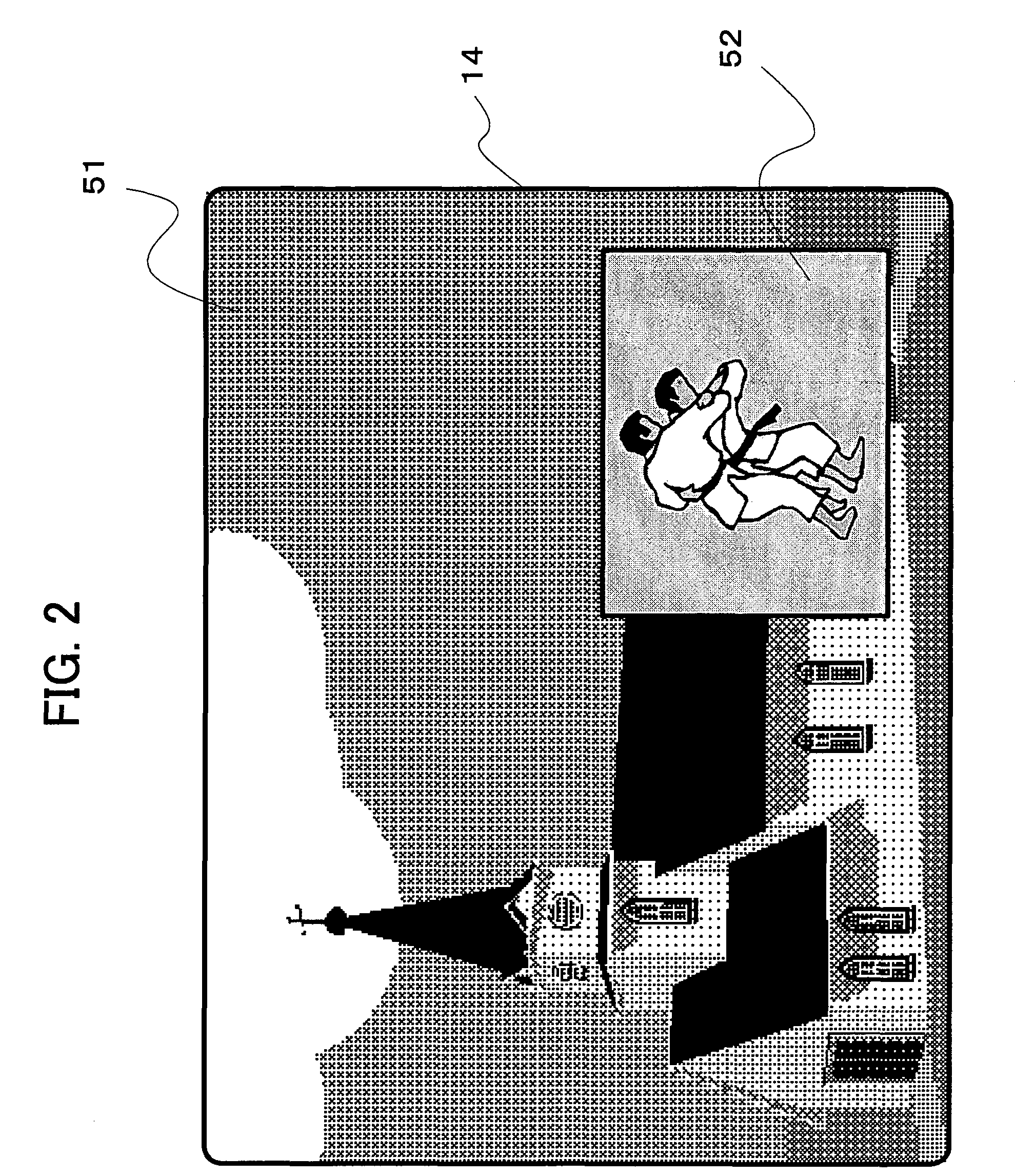
[0073]FIG. 8 is a view showing a displayed screen 14 of a broadcast receiver such as a television receiver according to the third embodiment of the present invention. As shown in FIG. 8, a message window 80, which indicates graphic data generated by the display processor 12, is displayed in the main-picture display area 51. The message window 80 includes selection buttons 81 and 82 that can be selected by the viewer using the remote controller or the like.

[0074]A method of reporting the occurrence of a highlight scene and ...


PUM


Abstract

A broadcast receiver includes a first video signal selector which outputs a video signal of a main-picture; a second video signal selector which outputs a video signal of a sub-picture; a first audio signal selector which outputs an audio signal of the main-picture; a second audio signal selector which outputs an audio signal of the sub-picture; a first video processor which generates a third video signal from the video signals of the main-picture and / or sub-picture; a feature quantity generator which generates a feature quantity of the audio signal of the sub-picture in accordance with a result of comparison between data corresponding to the audio signal of the sub-picture and sound class model data created beforehand; a determination processor which determines a scene as a specified scene; and a controller which controls the whole components in accordance with the specified scene.

Description

BACKGROUND OF THE INVENTION[0001]1. Field of the Invention[0002]The present invention relates to a broadcast receiver such as a television receiver which receives a plurality of video / audio signals.[0003]2. Description of the Related Art[0004]Some television receivers have a picture-in-picture (PinP) function for displaying a main-picture (also referred to as a parent picture) and a sub-picture (also referred to as a child picture) simultaneously in a single image display screen. When the PinP function is used, the speaker usually outputs the sound of the main-picture and does not output the sound of the sub-picture. For example, the user (i.e., viewer) can view and enjoy a drama or a movie with sound in the main-picture while watching a program, the highlight scenes (such as a scoring scene) of which would be worthy of watching, such as a sports program, without sound output, and can switch between the main-picture and the sub-picture as necessary. With this type of use, however, t...

Claims


Application Information

Patent Timeline
Patent Type & Authority Patents(United States)
IPC IPC(8): H04N5/45H04N5/44
CPCH04N5/45H04N5/60H04N21/4882H04N21/4316H04N21/4394H04N21/482H04N21/4263H04N21/4221
Inventor OTSUKA, ISAOSUGINOHARA, HIDETSUGU
Owner MITSUBISHI ELECTRIC CORP
Why Eureka
Try Eureka