
Imaging environment recognition device

a technology of environment recognition and image, which is applied in scene recognition, television systems, instruments, etc., can solve the problems of difficult detection of traffic lane itself, degree of defocus not allowing the detection of water droplets deposited on the lens, and the inability to detect the traffic lane itsel

Active Publication Date: 2011-07-19
HITACHI ASTEMO LTD
View PDF13 Cites 30 Cited by
  • Summary
  • Abstract
  • Description
  • Claims
  • Application Information

AI Technical Summary

Benefits of technology

The system effectively detects and alerts drivers to poor imaging conditions, ensuring proper operation of obstacle detection systems by adjusting parameters for accurate feature recognition and preventing erroneous operations due to improved image sharpness and clarity.

Problems solved by technology

As a result, the degree of defocus does not allow the water droplets deposited on the lens to be detected.
Further, if the image is largely distorted or severely defocused, it becomes difficult to detect the traffic lane itself.
Another problem is that, if the type of traffic lane and faint paint or other paint conditions are not identified, the degree of defocus may be wrongly calculated or incorrectly compared.

Method used


Image

  • Imaging environment recognition device
  • Imaging environment recognition device
  • Imaging environment recognition device

Examples


first embodiment

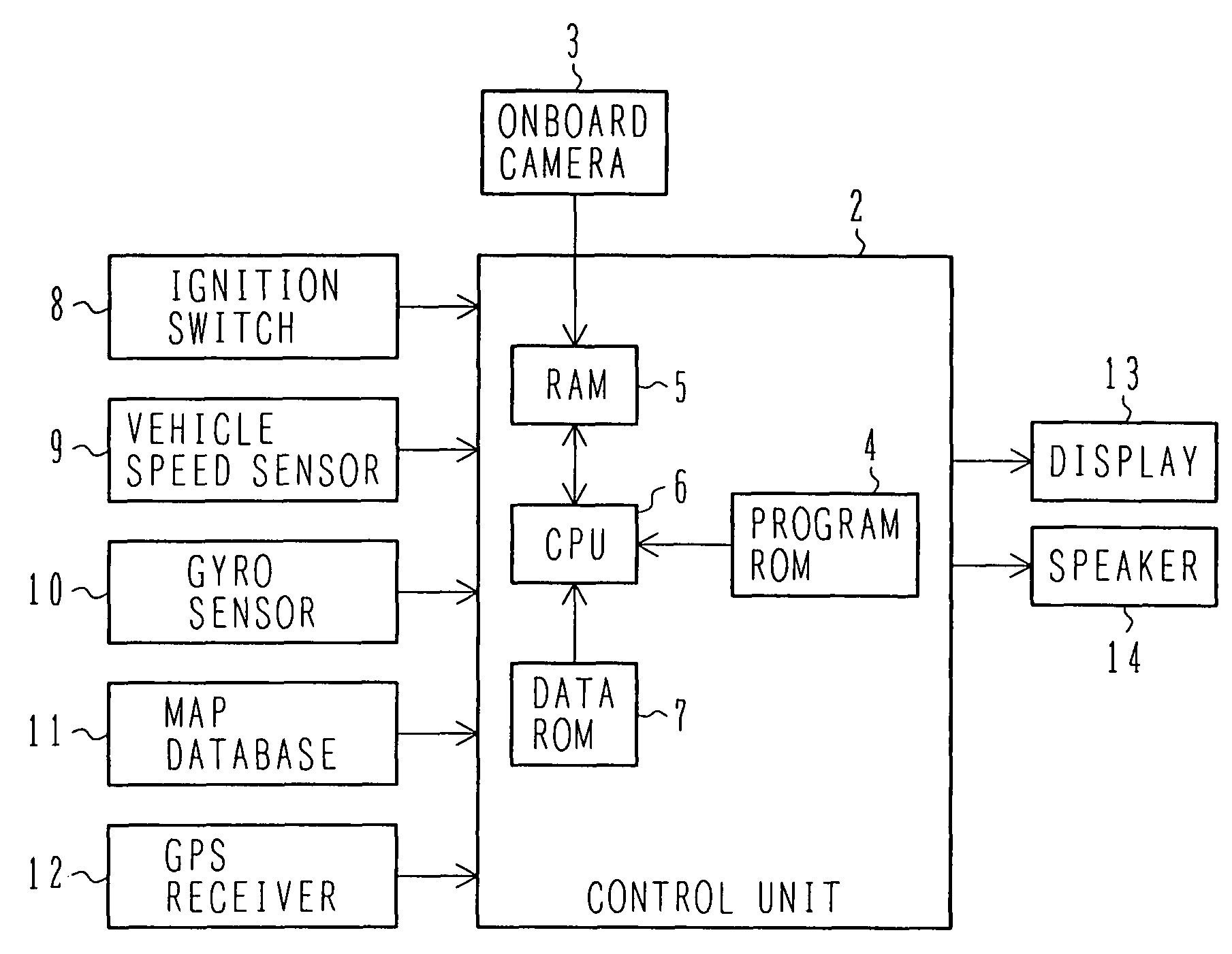
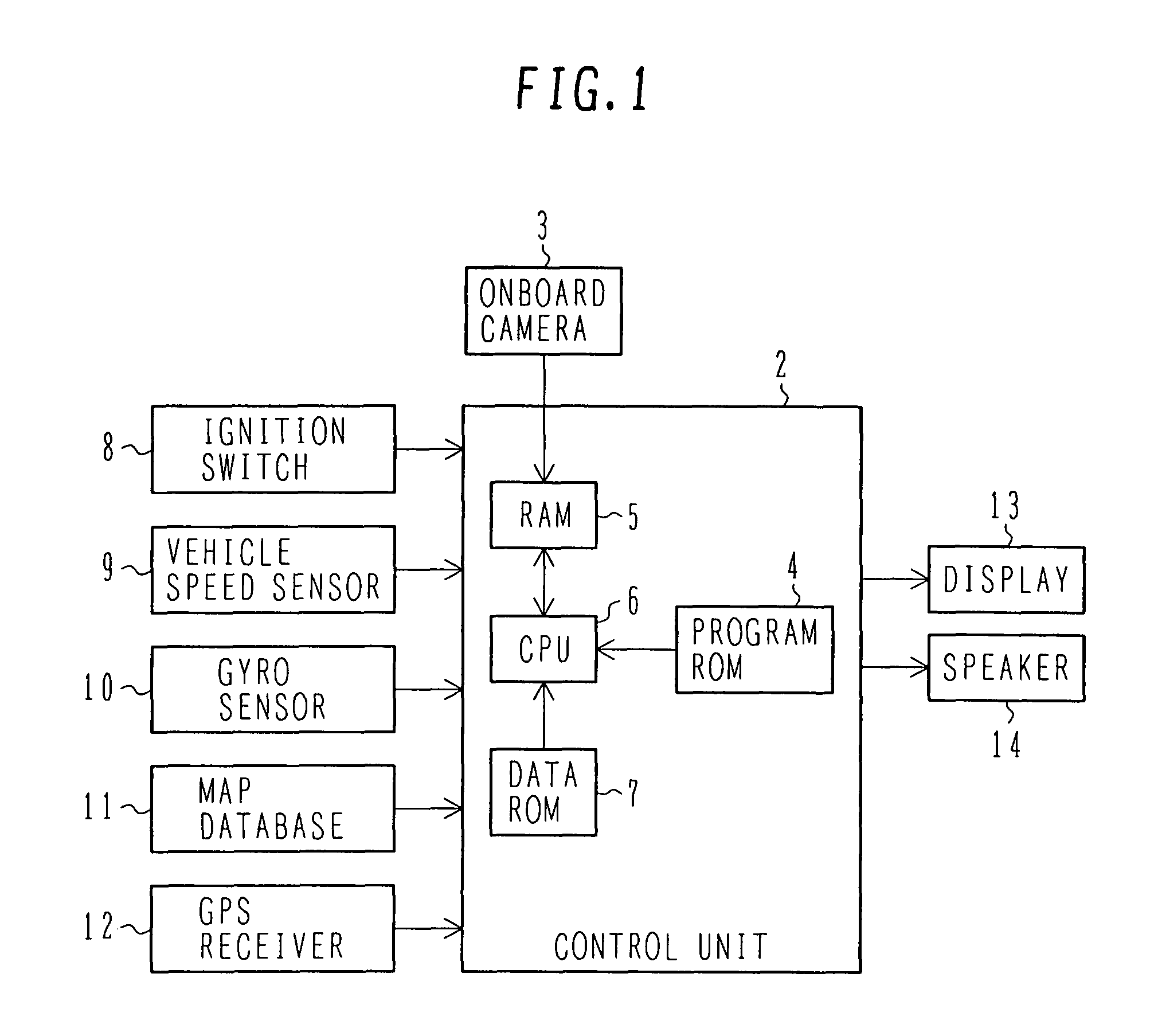
[0023]FIG. 1 is a block diagram showing a vehicle-mounted onboard system incorporating an imaging environment recognition device according to an embodiment of the present invention. The imaging environment recognition device according to the embodiment of the present invention achieves the function of recognizing environment surrounding the vehicle using an onboard camera 3 included in the onboard system. The onboard system shown in FIG. 1 detects a position of the vehicle, in which the system is mounted (hereinafter referred to as “host vehicle”). The onboard system also presents information of various sorts concerning guiding of a traveling path and obstacles present forward of the host vehicle. The onboard system includes the onboard camera 3, a display 13, a speaker 14, and a control unit 2. The onboard camera 3, disposed on an outside of the host vehicle, takes images forward of the host vehicle. The display 13, disposed on an inside of the host vehicle, displays images and inf...

second embodiment

[0052]A second embodiment of the present invention will be described below. For arrangements of the onboard system according to the second embodiment of the present invention, like parts as those used in the arrangements according to the first embodiment of the present invention are identified by like reference numerals and detailed descriptions for the same will be omitted.

[0053]FIG. 9 is a block diagram showing a vehicle-mounted onboard system according to the second embodiment of the present invention. An onboard camera 3 that achieves the function of recognizing the environment surrounding the vehicle in the onboard system according to the second embodiment of the present invention is disposed such that part of the vehicle falls within the field of view, as compared with the onboard camera 3, which is included in the onboard system according to the first embodiment of the present invention and which is disposed on the outside of the host vehicle at the leading end portion thereo...


PUM


Abstract

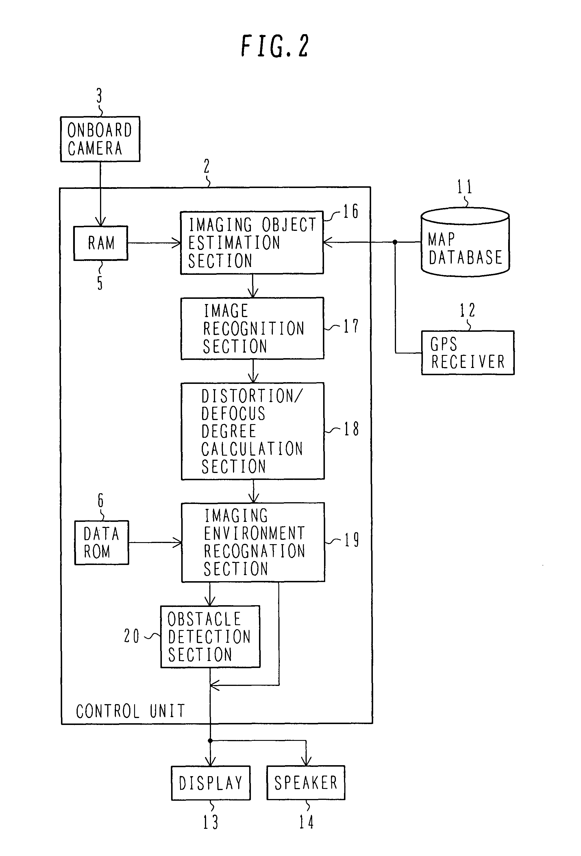
An imaging environment that greatly affects image recognition accuracy is recognized for applications in onboard systems of various sorts including imaging devices.An imaging device for imaging areas around the vehicle is mounted on a vehicle. Before executing image recognition processing, information is acquired on objects and texture, such as traffic signs and pedestrian crossings, present within a field of view of the imaging device. An object or texture present within the field of view is then recognized by an image recognition section. Degrees of distortion and defocus of a shape or texture of the object recognized are calculated based on the shape or texture of the object recognized and information previously acquired on the objects or texture. Imaging environment, such as water droplets or dirt on a lens, and whether fog occurs or not, is then recognized based on the degrees of distortion and defocus calculated from the shape or texture of the object recognized.

Description

BACKGROUND OF THE INVENTION[0001]1. Field of the Invention[0002]The present invention relates to an imaging environment recognition device that provides a vehicle onboard system using an onboard camera, such as an obstacle detection system or a parking support system, with necessary environmental information by using an imaging means, such as a camera, for imaging road conditions surrounding the vehicle and processing the image taken to recognize imaging environment.[0003]2. Description of the Related Art[0004]Research and development activities have been underway for recent years to provide automatic driving of vehicles and vehicle driving aid. Techniques have being studied for notifying drivers of the presence of a pedestrian by processing images taken by an onboard camera for detecting pedestrians. Techniques are also being studied for providing driving aid by detecting obstacles, traffic lights, and traffic signs.[0005]When images are taken by such an onboard camera, fog may occ...

Claims


Application Information

Patent Timeline
Patent Type & Authority Patents(United States)
IPC IPC(8): G06K9/00
CPCG05D1/0246G06K9/00805G06K9/00798G06V20/588G06V20/58
Inventor HIGUCHI, MIRAIYOKOTA, SOICHIRO
Owner HITACHI ASTEMO LTD
Learn More