Method for determining the centrality of masks

a mask and centrality technology, applied in the field of mask centrality determination, can solve the problems of increasing the requirements for accuracy and measurement throughput, increasing the risk of damage, and directly adding errors in this process to the error budget of the lithography process. , to achieve the effect of avoiding damage and increasing accuracy

Active Publication Date: 2011-07-26
VISTEC SEMICON SYST
View PDF17 Cites 2 Cited by
  • Summary
  • Abstract
  • Description
  • Claims
  • Application Information

AI Technical Summary

Benefits of technology

[0013]It is an object of the invention to provide a measuring method with which properties of a mask may be determined with increased accuracy. The risk of damage should be avoided, and the throughput of masks to be measured should be maintained at a high level.

Problems solved by technology

Errors made in this process are directly added to the error budget of the lithography process.
This method is not beneficial to achieving a high throughput in mask measuring.
However, each new chip generation has increased requirements regarding accuracy and measurement throughput.
The accuracy achievable by manual measurement using a conventional microscope is no longer sufficient.
In addition, the manual measurement requires a lot of time for the alignment in the measuring device, the locating of the structures and the actual measuring.
If this is the case, the mask does no longer have to be transported from one measuring device to the other, which ultimately represents an error source for damage to the mask.

Method used


Image

  • Method for determining the centrality of masks
  • Method for determining the centrality of masks
  • Method for determining the centrality of masks

Examples


Embodiment Construction

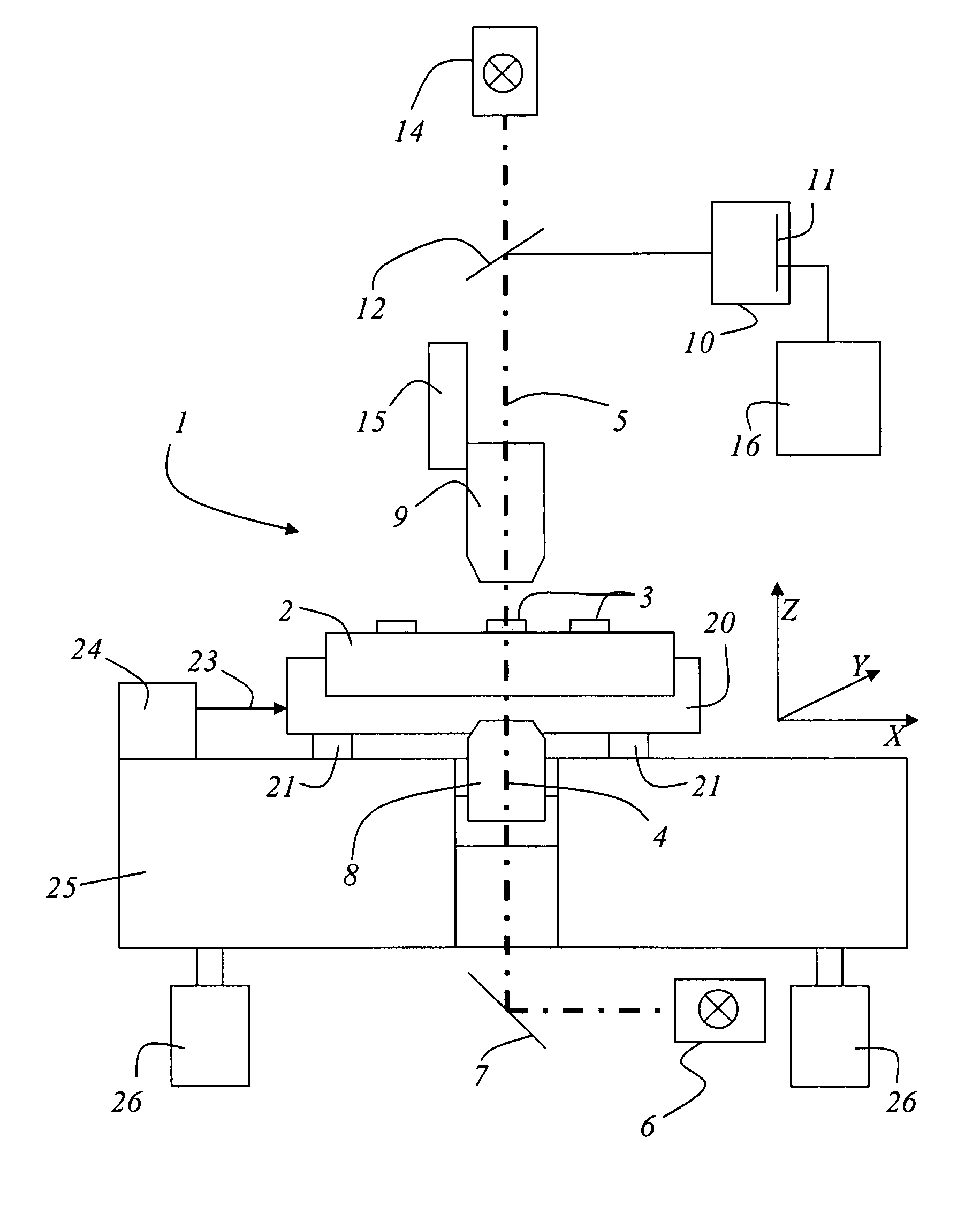
[0036]A coordinate measuring device with which the inventive method is performed is shown in FIG. 1 and has already been described in detail with respect to the prior art. The coordinate measuring device 1 includes a measurement table 20 movable in the X-coordinate direction and in the Y-coordinate direction. The measurement table 20 carries a substrate or a mask 2 for the semiconductor production. Several structures 3 are applied to a surface of the mask 2. The measurement table itself is supported by air bearings 21 which, in turn, are supported by a granite block 25. The use of a granite block 25 does not limit the invention in any way. It is obvious for someone skilled in the art that other materials may also be used if they have a corresponding plane in which the measurement table 20 may be moved. At least one incident light illumination means or device 14 and / or one transmitted light illumination means or device 6 are provided for the illumination of the mask 2. In the embodim...


PUM


Abstract

A method for determining the centrality of masks is disclosed. The mask is positioned in a coordinate measuring device on a measurement table displaceable in a direction perpendicular to the optical axis of an imaging measurement system in an interferometrically measurable way. The position of a mask coordinate system with respect to the measuring device coordinate system is determined based on at lest two structures on the mask. The relative distance from one of the at least first and second outer edges to the at least two structures is determined. The coordinate measuring machine determines the actual coordinates of the at least two structures with respect to the respective outer edges, which must not exceed a predetermined deviation from a desired value.

Description

[0001]This claims the benefit of German Patent Application No. 10 2007 049 100.1, filed Oct. 11, 2007 and hereby incorporated by reference herein.[0002]The present invention relates to a method for determining the centrality of masks. For the inventive method, the mask is positioned in a coordinate measuring device on a measurement table displaceable in a direction perpendicular to the optical axis of an imaging measurement system in an interferometrically measurable way. The coordinate measuring device determines a measuring device coordinate system.BACKGROUND[0003]German Patent DE 198 17 714 discloses a method for measuring the position of structures on a mask surface, wherein the mask is positioned in an image-evaluating coordinate measuring device on a measurement table displaceable in a direction perpendicular to the optical axis of an imaging measurement system in an interferometrically measurable way. A mask coordinate system associated with the mask is aligned relative to a ...

Claims


Application Information

Patent Timeline
Patent Type & Authority Patents(United States)
IPC IPC(8): G01B11/00G01B11/14G06K9/00
CPCG01B11/005G03F1/84G03F9/7007G06T7/0042G06T7/0044G06T7/0083G06T2207/30148G06T7/73G06T7/74G06T7/12
Inventor HEIDEN, MICHAEL
Owner VISTEC SEMICON SYST
Why Eureka
Try Eureka