Flexible stent

a flexible, stent technology, applied in the field of expandable tubular structures, can solve the problems of complicated interconnection of helical strut bands, etc., and achieve the effect of substantial flexibility and complicating changing the diameter state of the sten

Active Publication Date: 2011-08-02
FLEXIBLE STENTING SOLUTIONS
View PDF3 Cites 30 Cited by
  • Summary
  • Abstract
  • Description
  • Claims
  • Application Information

AI Technical Summary

Benefits of technology

[0009]The stent of the present invention combines a helical strut member or band interconnected by coil elements. This structure provides a combination of attributes that are desirable in a stent, such as, for example, substantial flexibility, stability in supporting a vessel lumen, cell size and radial strength. However, the addition of the coil elements interconnecting the helical strut band complicates changing the diameter state of the stent. Typically a stent structure must be able to change the size of the diameter of the stent. For instance, a stent is usually delivered to a target lesion site in an artery while in a small diameter size state, then expanded to a larger diameter size state while inside the artery at the target lesion site. The structure of the stent of the present invention provides a predetermined geometric relationship between the helical strut band and interconnected coil elements in order to maintain connectivity at any diameter size state of the stent.

Problems solved by technology

However, the addition of the coil elements interconnecting the helical strut band complicates changing the diameter state of the stent.

Method used


Image

  • Flexible stent
  • Flexible stent
  • Flexible stent

Examples


Embodiment Construction

[0023]Reference will now be made in greater detail to a preferred embodiment of the invention, an example of which is illustrated in the accompanying drawings. Wherever possible, the same reference numerals will be used throughout the drawings and the description to refer to the same or like parts.

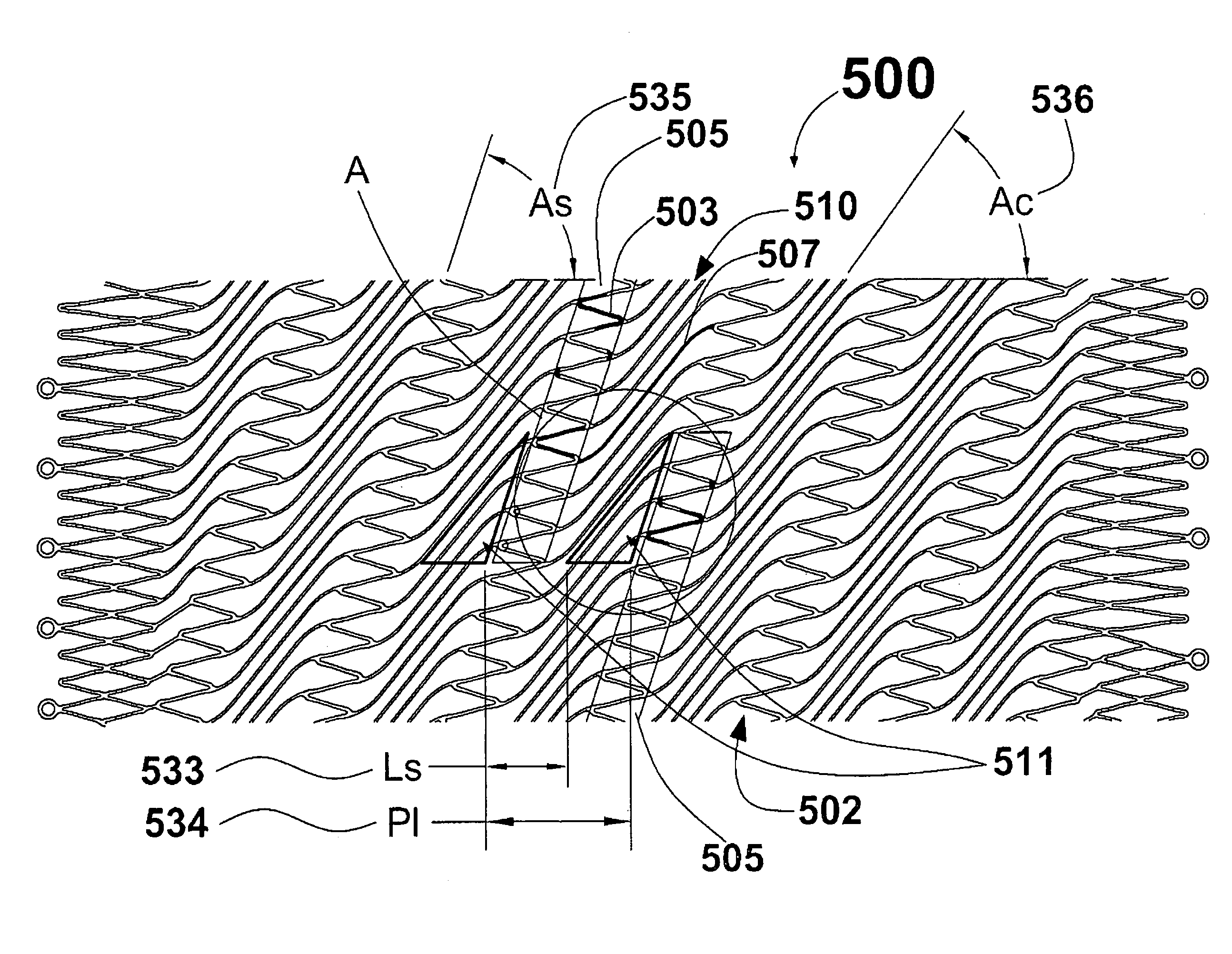
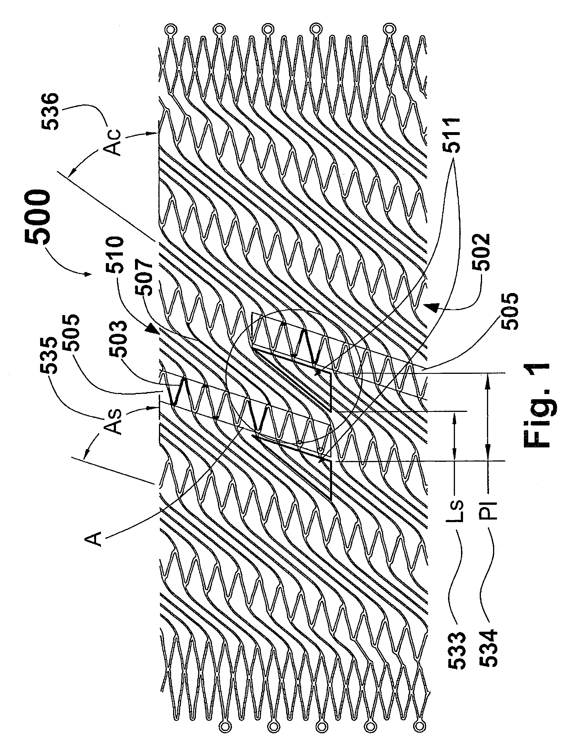
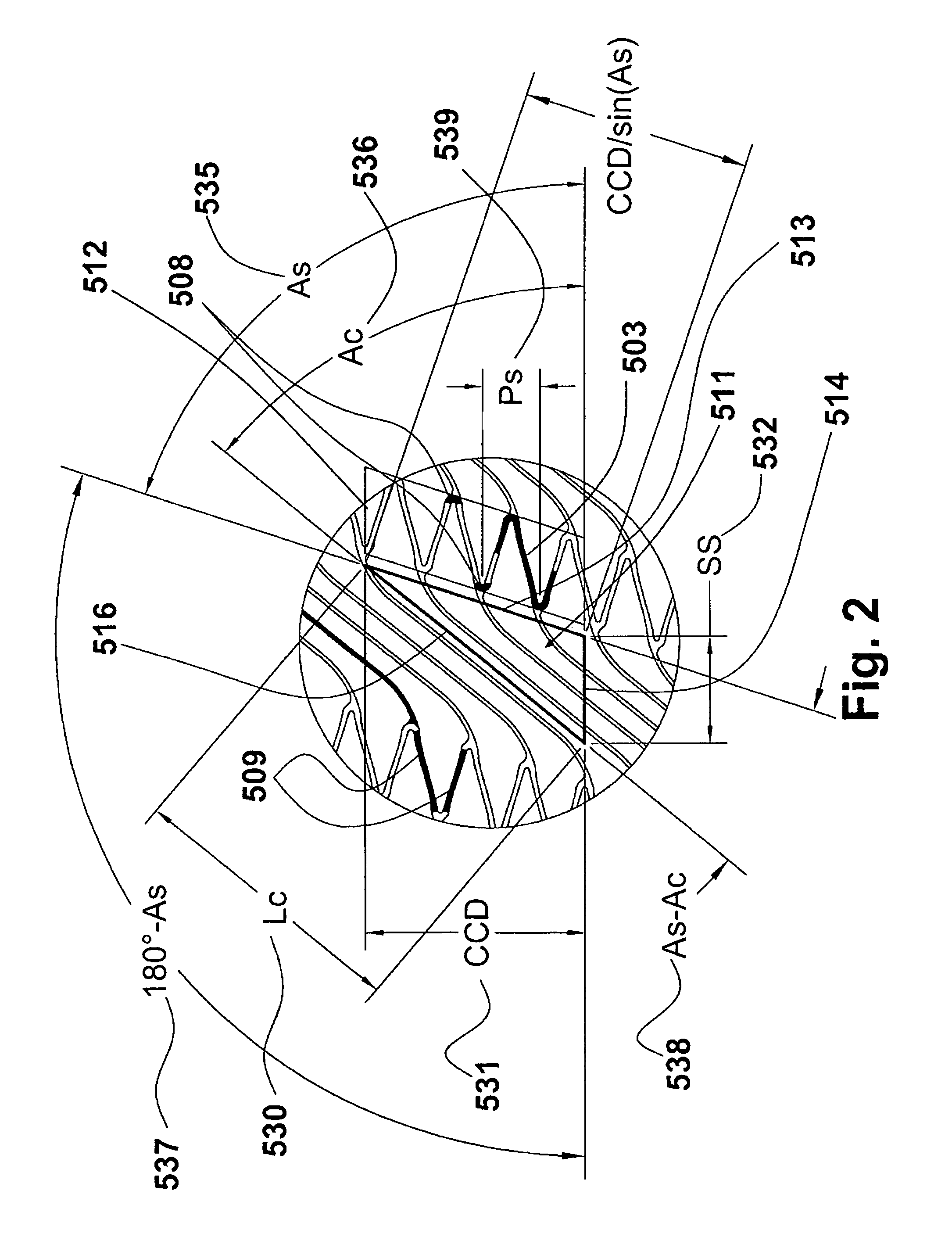
[0024]FIG. 1 with detail shown in FIG. 2 illustrates stent 500. FIG. 1 is a plan view of a first embodiment of stent 500 in accordance with the present invention shown in a partially expanded state. As used herein, the term “plan view” will be understood to describe an unwrapped plan view. This could be thought of as slicing open a tubular stent along a line parallel to its axis and laying it out flat. It should therefore be appreciated that, in the actual stent, the top edge of FIG. 1 will be joined to the lower edge. Stent 500 is comprised of helical strut band 502 interconnected by coil elements 507. Side-by-side coil elements 507 form coil band 510. Coil band 510 is formed as a double ...


PUM


Abstract

The stent of the present invention combines a helical strut band interconnected by coil elements. This structure provides a combination of attributes that are desirable in a stent, such as, for example, substantial flexibility, stability in supporting a vessel lumen, cell size and radial strength. The structure of the stent of the present invention provides a predetermined geometric relationship between the helical strut band and interconnected coil elements in order to maintain connectivity at any diameter size state of the stent.

Description

CROSS REFERENCE TO RELATED APPLICATION[0001]This application is claims the benefit of U.S. Provisional Patent Application No. 60 / 963,083 filed Aug. 2, 2007 and U.S. Provisional Patent Application No. 61 / 070,598 filed Mar. 24, 2008 the entirety of both of are hereby incorporated by reference into this application.BACKGROUND OF THE INVENTION[0002]1. Field of the Invention[0003]The present invention relates generally to expandable tubular structures capable of insertion into small spaces in living bodies and, more particularly, concerns a stent structure having a geometry which is capable of substantial and repeated flexing at points along its length without mechanical failures and with no substantial changes in its geometry.[0004]2. Description of the Related Art[0005]A stent is a tubular structure that, in a radially compressed or crimped state, may be inserted into a confined space in a living body, such as a duct, an artery or other vessel. After insertion, the stent may be expande...

Claims


Application Information

Patent Timeline
Patent Type & Authority Patents(United States)
IPC IPC(8): A61F2/06
CPCA61F2/915A61F2/88A61F2230/0054A61F2002/91558A61F2002/91575A61F2002/91525
Inventor BEACH, BRADLEYBURPEE, JANET
Owner FLEXIBLE STENTING SOLUTIONS
Why Eureka
Try Eureka