
Display apparatus

a technology of display apparatus and pixel, applied in the direction of instruments, static indicating devices, etc., can solve the problem of insufficient application of the voltage of the image signal to the pixel

Inactive Publication Date: 2011-08-02
SHARP KK
View PDF27 Cites 6 Cited by
  • Summary
  • Abstract
  • Description
  • Claims
  • Application Information

AI Technical Summary

Benefits of technology

The solution allows for sufficient pixel charging time even during sub-frame driving, reducing image blur and enhancing display quality by ensuring longer voltage application to pixels and maintaining consistent sub-frame periods, which improves the overall moving image display.

Problems solved by technology

This makes it impossible to sufficiently apply the voltage of an image signal to a pixel.

Method used


Image

  • Display apparatus
  • Display apparatus
  • Display apparatus

Examples


Embodiment Construction

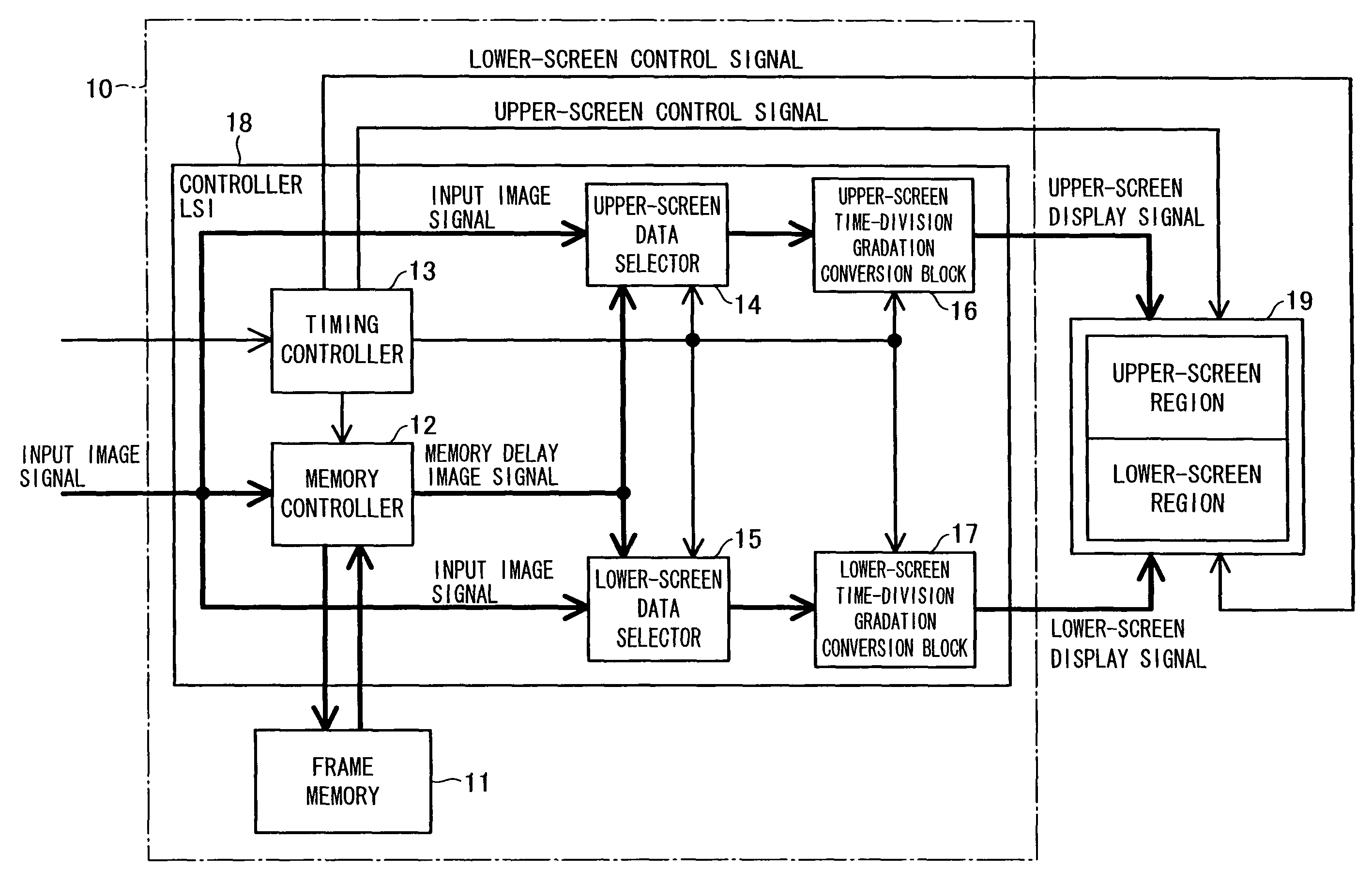
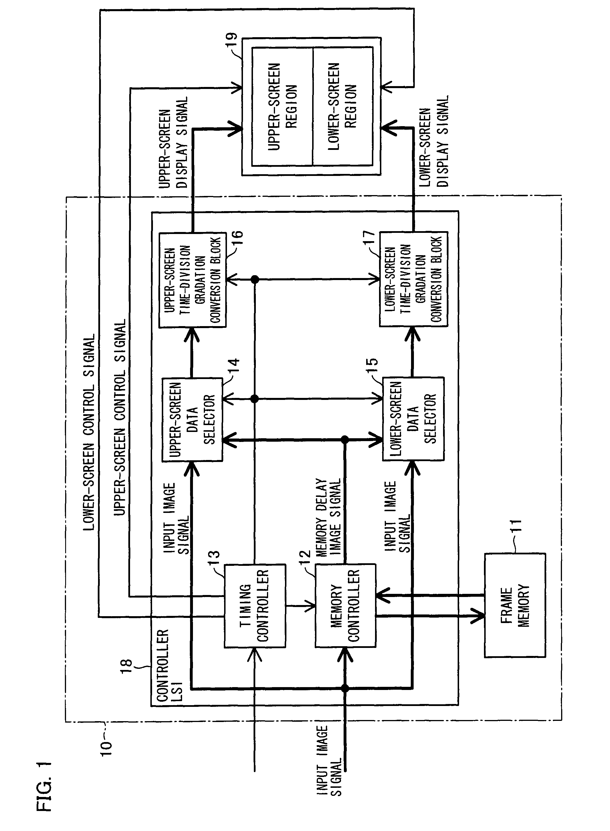
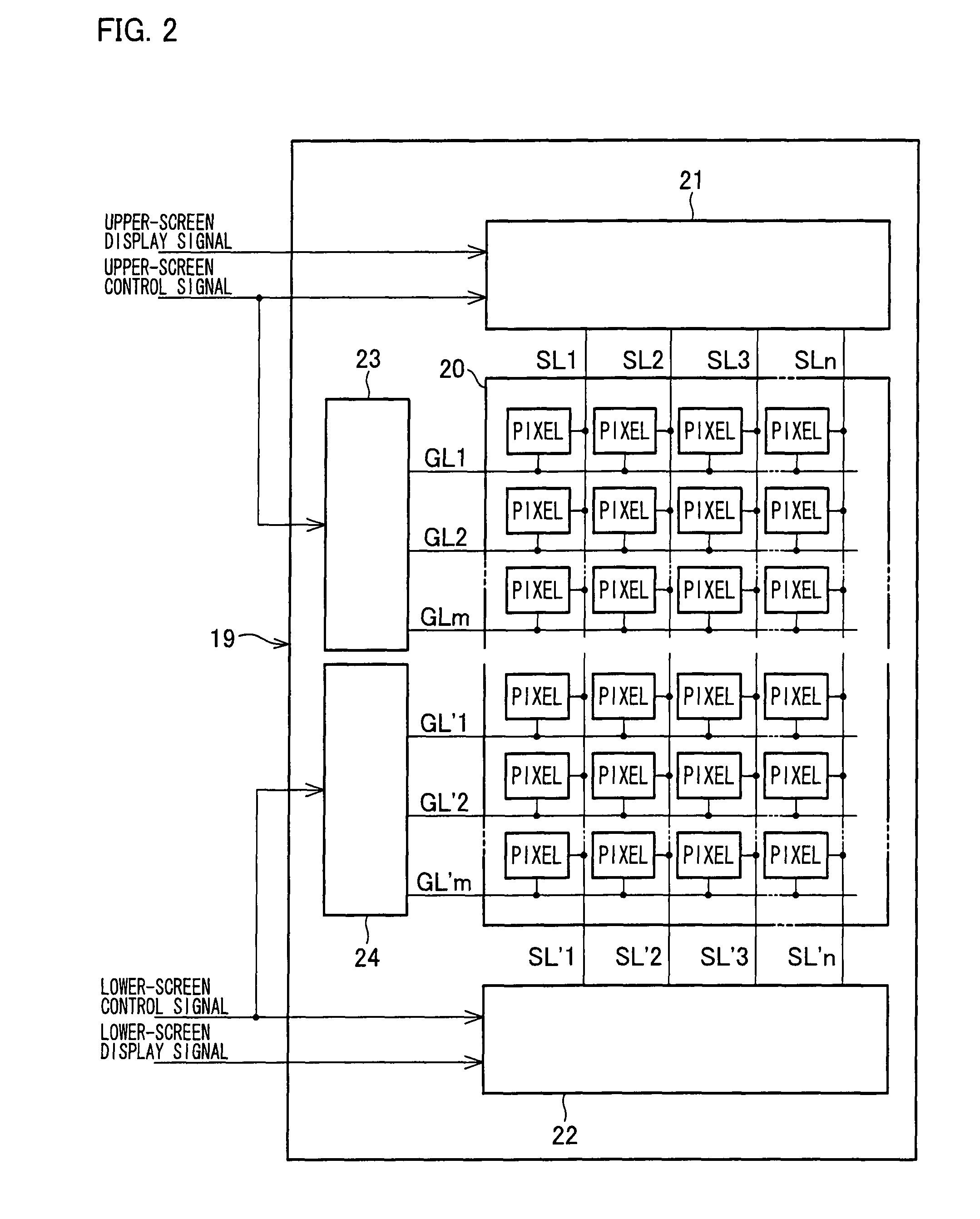
[0080]An embodiment of the present invention will be described below with reference to FIGS. 1 through 8.

[0081]That is, a display apparatus according to the present embodiment (such a display apparatus being hereinafter referred to as “present image display apparatus”) is a display apparatus in which sufficient pixel charging time is obtained even when sub-frames into which a frame has been time-divided are driven, and can be suitably applied, for example, to a television receiver and a display monitor that is to be connected a personal computer.

[0082]Note that examples of television broadcasts to be received by such a television receiver include (i) broadcasts, such as terrestrial television broadcasts, BS (Broadcasting Satellite) digital broadcasts, and CS (Communication Satellite) digital broadcasts, which are provided via satellites or (ii) cable television broadcasts.

[0083]As shown in FIG. 1, the present image display apparatus includes a display module 19 and a control sectio...


PUM


Abstract

In one embodiment of the present invention, a display module includes a display screen divided in a vertical direction into screen regions in each of which an image can be independently displayed. A control device for controlling an image display operation of the display module includes: upper- and lower-screen data selectors for each dividing an input image signal in accordance with a corresponding one of the screen regions; and upper- and lower-screen time-division gradation conversion blocks for each generating a display signal for each of a plurality of sub-frames from an image signal, corresponding to a corresponding one of the screen regions, which is outputted from a corresponding one of the data selectors. This makes it possible to provide an image display device in which, even when a sub-frame display is carried out, the voltage of an image signal can be applied to a pixel for a longer time so as to be sufficiently applied to the pixel.

Description

TECHNICAL FIELD[0001]The present invention relates to an image display which, by time-dividing, into a plurality of sub-frames, a single frame that displays a single image, and by displaying, in a single frame period, images respectively corresponding to the plurality of sub-frames, displays an image corresponding to the single frame.BACKGROUND ART[0002]In recent years, hold display apparatuses including liquid crystal display modules and / or EL display modules have gone into use in a field where CRTs (cathode-ray tubes) have been used.[0003]However, it is said that such a hold display apparatus is inferior in quality of a moving image to an impulse display apparatus, such as a CRT (cathode-ray tube), in which an ON period during which an image is displayed and an OFF period during which no image is displayed are alternately repeated.[0004]That is, in a typical hold display apparatus, the whole of one frame period corresponds to an ON period, so that an update of a frame image cause...

Claims


Application Information

Patent Timeline
Patent Type & Authority Patents(United States)
IPC IPC(8): G09G3/36
CPCG09G3/3666G09G2310/0224G09G2320/0261
Inventor ISHIHARA, TOMOYUKI
Owner SHARP KK
Learn More