

Spectacles having retractable sidepieces
a technology of sidepieces and spectacles, which is applied in the field of spectacles, can solve the problems of unintentional lengthening or shortening of sidepieces, loss of stiffness of sidepieces,
- Summary
- Abstract
- Description
- Claims
- Application Information
AI Technical Summary
Benefits of technology
Problems solved by technology
Method used
Image

Examples
first embodiment
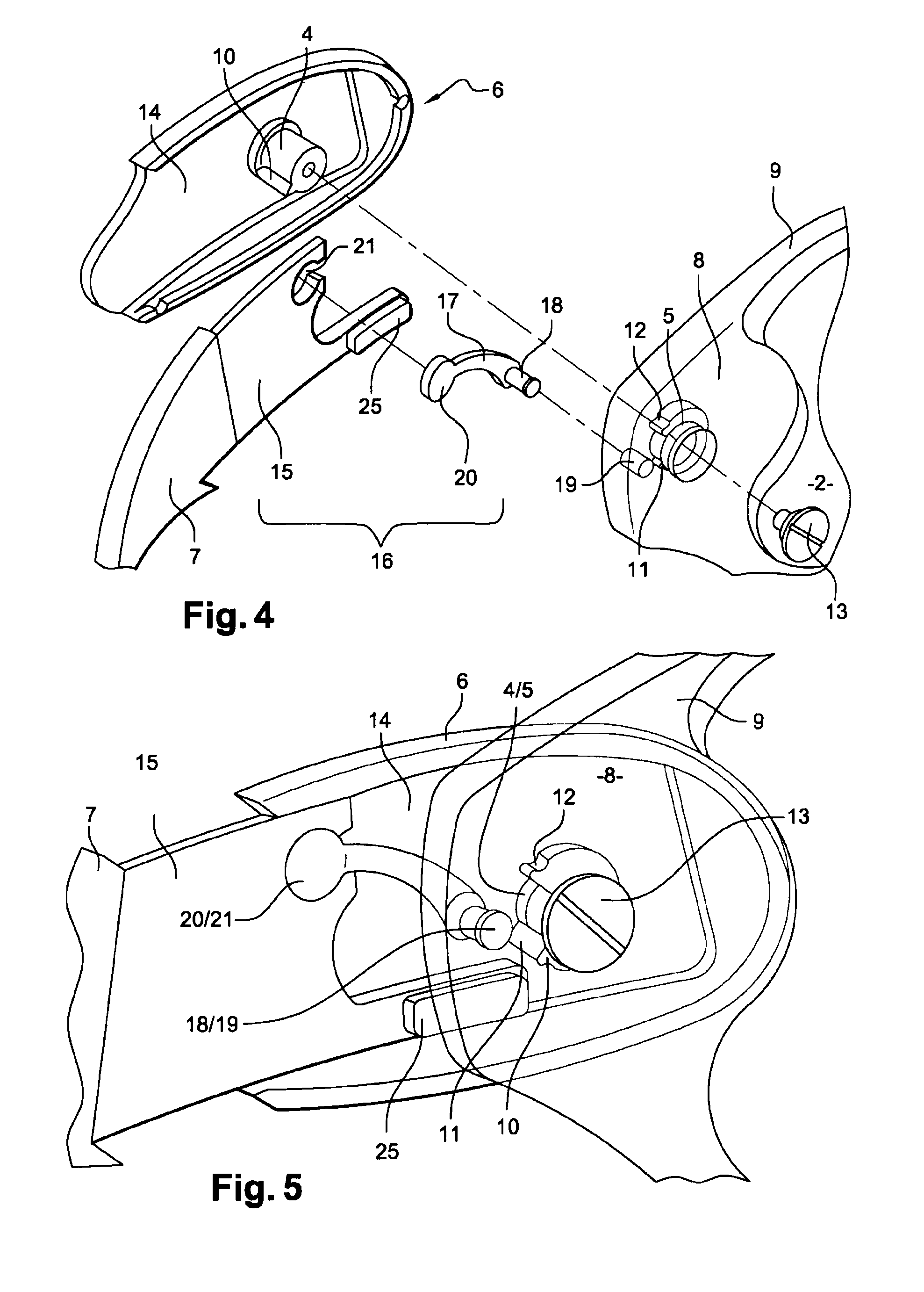
[0030]In a first embodiment represented in FIGS. 4 to 9, the means 16 for driving the second part 7 of the sidepiece 3 in translation during the rotation consist of a link 17. This is disposed between on the one hand a fixed articulation point 18, 19 situated at the end 8 of the frame 9 eccentrically relative to the rotation pin 4, 5 of said first part 6 and on the other hand another, this time mobile articulation point 20, 21 situated at the end of the second part 7 of the sidepiece 3 and offset relative to the longitudinal axis XX′. Said link 17 has a radius of curvature adapted to allow pivoting in rotation of the whole of the first part 6 and the second part 7 of the sidepiece 3 through an angle of substantially 180° while simultaneously allowing linear movement in translation of the second part 7 relative to the first 6.
[0031]To be more precise, the fixed articulation point of the link 17 consists of a first pin 18 produced at one end thereof cooperating in rotation with a hole...
second embodiment
[0034]In a second embodiment shown in FIG. 10, the means for driving the second part 7 of the sidepiece 3 in translation during the rotation consist of a toothed wheel 27 fixed onto the central pin 4 of the first part 6 of the sidepiece 3, which toothed wheel 27 is driven one way or the other by a mobile linear drive rack 28 produced in the guiding end area 15 of the second part 7 of the sidepiece 3.
third embodiment
[0035]In the third embodiment represented in FIG. 11, the means for driving the second part 7 of the sidepiece 3 in translation during the rotation consist of a cam 29 fixed onto the central pin 4 of the first part 6 of the sidepiece 3 and on the external ramp 30 of which cam 29 bears a front plane 31 of the guiding end area 15 of the second part 7 of the sidepiece 3 for linear actuation thereof one way or the other.
[0036]As may be seen in FIG. 11, a return spring 32 operates in tension between the pin 4 and a fixed point 33 situated in the guiding end area 15.
[0037]There is also provided a stop for stopping rotation of the sidepiece by means of a plane 34 perpendicular to the front plane 31 on which a corresponding plane 35 of the cam 29 disposed substantially radially relative to its axis comes to bear.
PUM
 Abstract
Description
Claims
Application Information