Cranial flap clamp instrument

a clamping instrument and cranial flap technology, applied in the field of instruments, can solve the problems of inconvenient use, inconvenient operation, and long time-consuming procedure, and achieve the effect of reducing the risk of injury, avoiding the possibility of bruising or cutting too deep holes, and avoiding the formation of bruising

Active Publication Date: 2011-08-09
SYNTHES USA
View PDF92 Cites 7 Cited by
  • Summary
  • Abstract
  • Description
  • Claims
  • Application Information

AI Technical Summary

Problems solved by technology

Disadvantages of this method include the tedious nature and length of time required for the procedure and the possibility of injury from drilling the holes too deep or from the sharp ends of the wires.
The disadvantages associated with the use of plates and screws relate to the undesirable cosmetic appearance resulting from the protrusion of the plate and screw above the bone surface.
As there is minimal intervening soft tissue between the skull and the skin, unappealing external appearance is particularly a problem.
The lack of soft tissue also has the unwanted consequence of permitting the patient to feel the plate and screw simply by pressing on the scalp.

Method used


Image

  • Cranial flap clamp instrument
  • Cranial flap clamp instrument
  • Cranial flap clamp instrument

Examples


Embodiment Construction

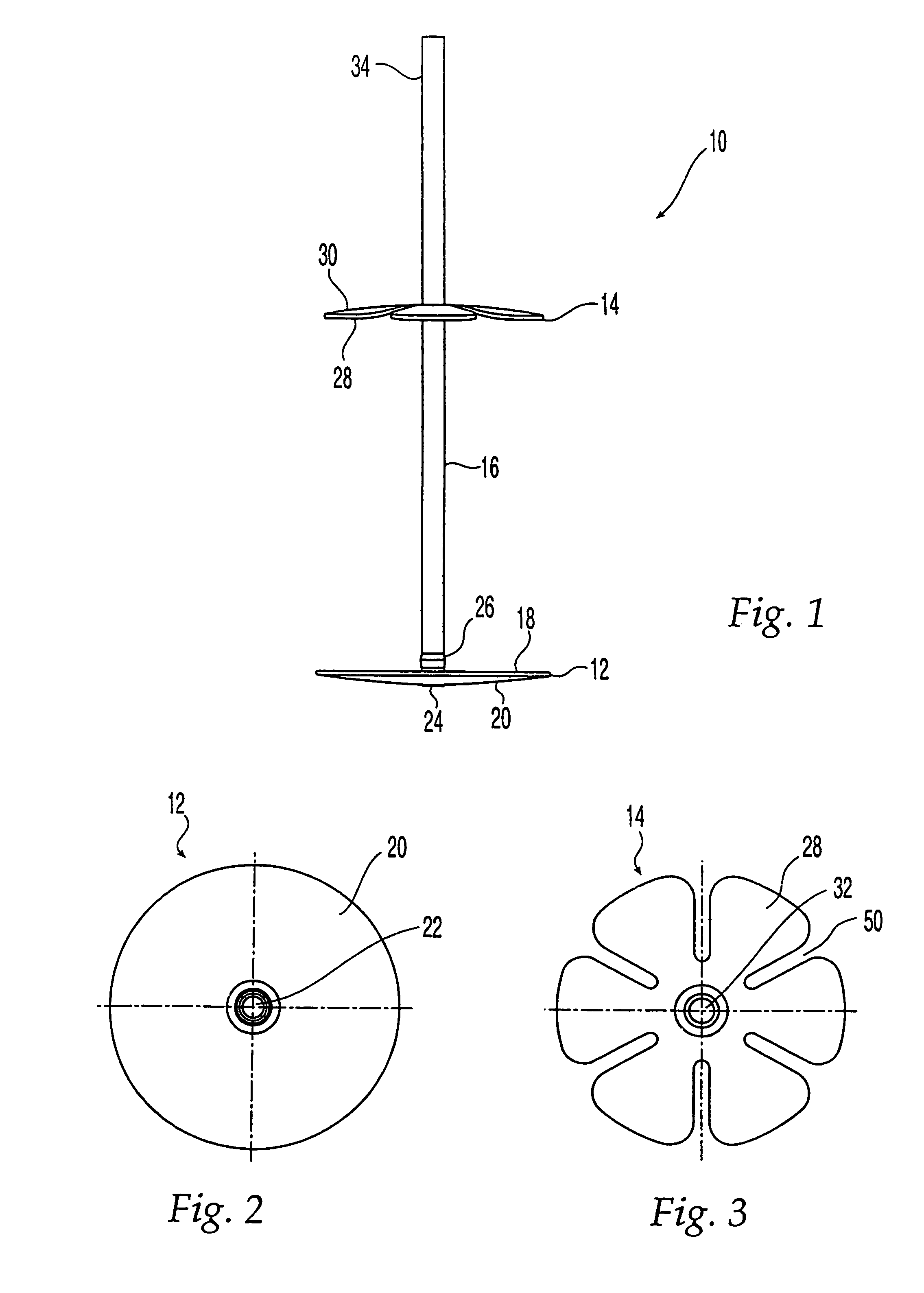
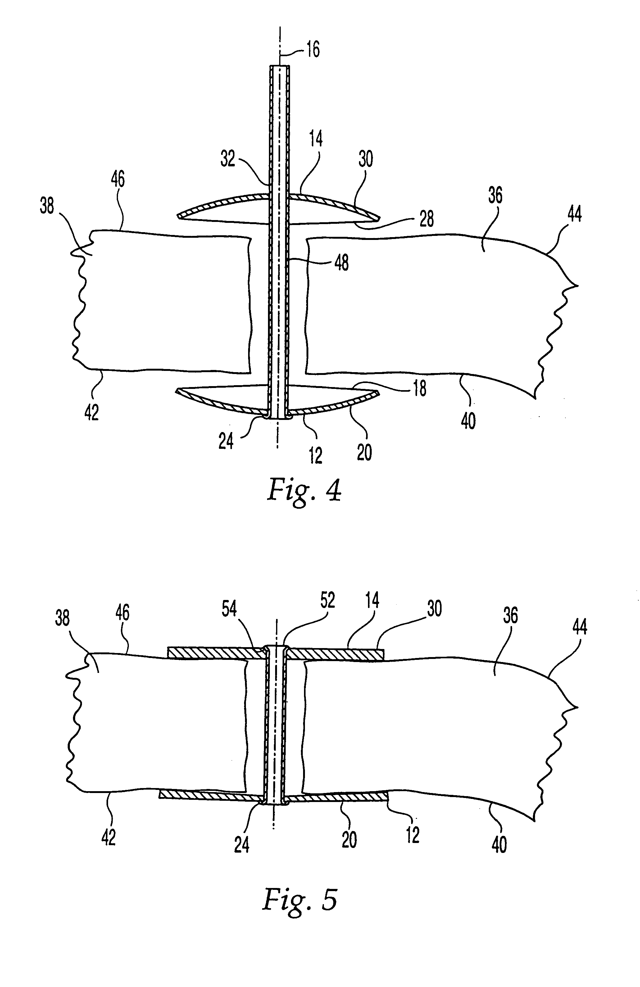
[0077]As shown in FIGS. 1-4, one embodiment of a cranial flap clamp 10 according to the present invention includes a first clamping member 12, a second clamping member 14, and an extension member 16. Cranial flap clamp 10 can be made of any suitable biocompatible material, such as stainless steel, titanium, a titanium based alloy, or a resorbable material. If cranial flap clamp 10 is made of a metallic material, preferably first and second clamping members 12, 14 and extension member 16 are made of the same material to minimize the potential for galvanic corrosion. First clamping member 12 has a disk shape with a concave inner surface 18 and a convex outer surface 20. Extension member 16 extends from inner surface 18 of first clamping member 12. Although extension member 16 is shown as a tube, extension member 16 can be any similar structure so long as the structure and material allow crimping, as explained below.

[0078]Extension member 16 can be integral to first clamping member 12....


PUM


Abstract

The disclosed cranial flap clamp includes first and second clamping members and an extension member. A portion of the first member is positionable against inferior surfaces of a bone flap and skull and a portion of the second member is positionable against superior surfaces of the flap and skull. The extension member extends from the first member through the second member and fits between the flap and skull. Movement of either of the clamping members urges the inner surface of the first member against the inferior surfaces of the flap and skull and urges the inner surface of the second member against the superior surfaces of the flap and skull. The securing instrument includes features useful in cutting or crimping the extension member. The tension limiting assembly provides variable designs and combinations for limiting the tension placed on, and exerted by, the securing instrument during use.

Description

CROSS-REFERENCE TO RELATED APPLICATIONS[0001]This is a continuation-in-part of U.S. Non-Provisional patent application Ser. No. 09 / 910,720, filed Jul. 24, 2001 now U.S. Pat. No. 7,361,178, which claims the benefit under 35 U.S.C. §119(e) of U.S. Provisional Patent Application No. 60 / 221,148, filed Jul. 27, 2000, the entirety of which applications are expressly incorporated herein by reference thereto.FIELD OF THE INVENTION[0002]The present invention is directed to an instrument for use with a cranial flap clamp for attaching a bone flap to a skull.BACKGROUND OF THE INVENTION[0003]Craniotomies are surgical procedures performed in the treatment of various brain problems, such as tumors, aneurysms, blood clots, head injuries, abscesses, and the like. During a craniotomy procedure, access to the brain is achieved by the creation of a hole in the bone that defines the skull. The hole or “window” in the skull is usually created by identifying the area of the brain to which access is neede...

Claims


Application Information

Patent Timeline
Patent Type & Authority Patents(United States)
IPC IPC(8): A61B17/58A61B17/84A61F2/00A61F2/08A61B17/00A61B17/68A61B17/88
CPCA61B17/688A61B17/88A61B17/8863A61B17/8869A61B2019/307A61B19/30A61B2017/00004A61B2017/00862A61B2090/037A61B90/03A61B17/58A61B17/56A61B17/128A61B17/122
Inventor HEARN, JAMES PMANTHORP, JOHN HKERR, SEAN HARMITAGE, BRYAN MONROBURNS, PAULWIGGER, URS
Owner SYNTHES USA
Why Eureka
Try Eureka