
Methods and devices for reducing hazardous air pollutants

a technology of hazardous air pollutants and applied in the direction of hydrogen sulfide, electrostatic separation, combustible gas purification/modification, etc., can solve the problems of large capital and maintenance costs, high energy consumption of air pollution control devices, and high energy consumption of many such air pollution control devices. achieve the effect of reducing pollution and reducing an initial amount of sulfur oxides

Active Publication Date: 2011-08-09
C QUEST TECH
View PDF81 Cites 9 Cited by
  • Summary
  • Abstract
  • Description
  • Claims
  • Application Information

AI Technical Summary

Benefits of technology

[0005]In various aspects, the present disclosure provides methods of reducing pollution generated by a combustion source. The methods include reducing an initial amount of sulfur oxides present in a fluid stream exiting a combustion source by contacting the fluid stream with a solid material formed by admixing a slag component having one or more reactive silicate compounds with a binder component. In various embodiments prior to contact with the solid material, the fluid stream has a temperature of less than about 600° F. (about 316° C.). Removal efficiency of the sulfur oxides present in the fluid stream is preferably above 20% and in various embodiments is even higher, reaching greater than or equal to about 70%, as compared to the initial amount of sulfur oxides present in the fluid stream prior to contact.
[0006]Another aspect of the disclosure provides a method of reducing pollution generated by a combustion source, comprising reducing an initial amount of nitrogen oxides present in a fluid stream exiting a combustion source by contacting the fluid stream with a solid material formed by admixing a slag component having one or more reactive silicate compounds with a binder component. Prior to contact with the solid material, the fluid stream has a temperature of less than about 600° F. (about 316° C.). The amount of nitrogen oxides present in the fluid stream after contact with the solid material is reduced by a removal efficiency of greater than or equal to about 20%, as compared to the initial amount of nitrogen oxides present in the fluid stream prior to contact.
[0007]Another embodiment of the present disclosure provides a method of reducing pollution generated by a combustion source, comprising reducing an initial amount of air pollutants comprising sulfur oxides, nitrogen oxides, and carbon dioxide, the air pollutants present in a fluid stream exiting a combustion source, by contacting the fluid stream with a solid material formed by admixing a slag component having one or more reactive silicate compounds with a binder component. In an exemplary embodiment, prior to contact with the solid material, the fluid stream has a temperature of less than about 600° F. (about 316° C.). The total amount of air pollutants present in the fluid stream after contact with the solid material is reduced by a removal efficiency of greater than or equal to about 20%, as compared to the initial total amount of air pollutants present in the fluid stream prior to contact.
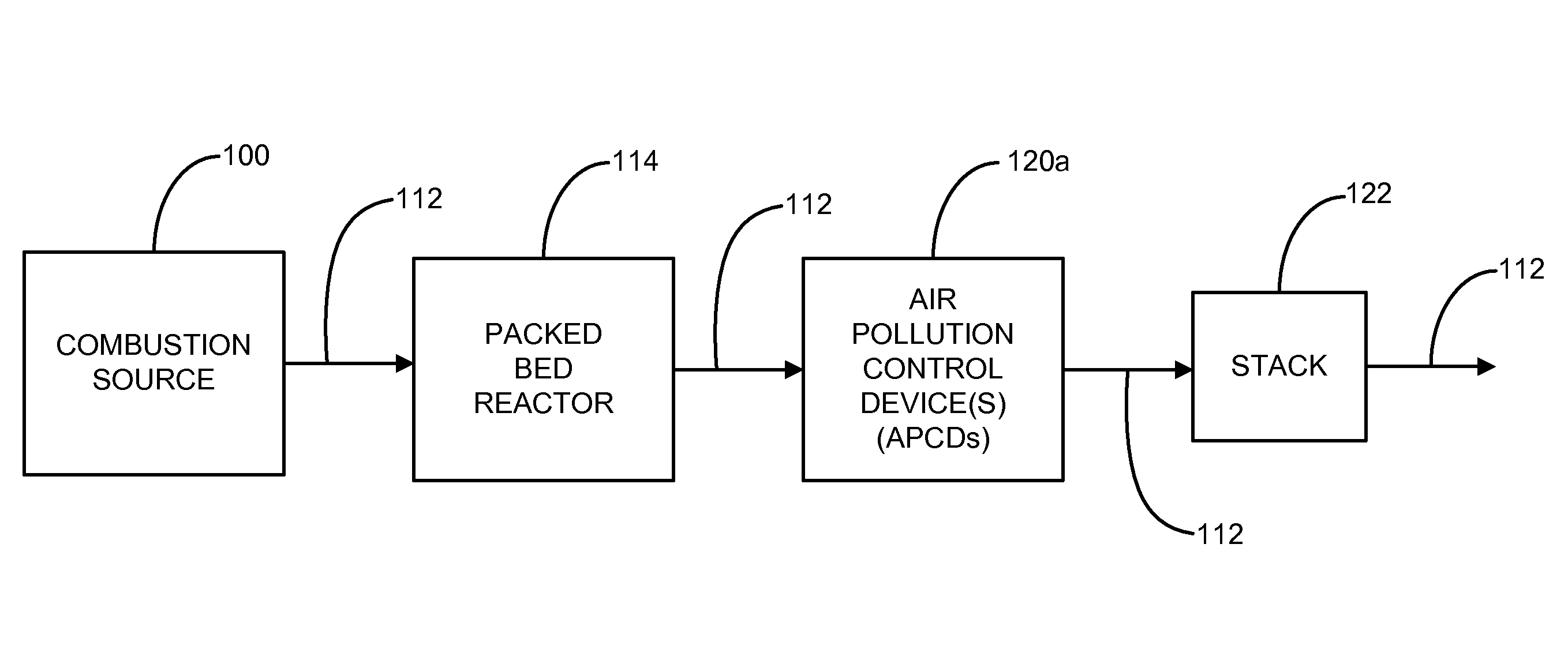
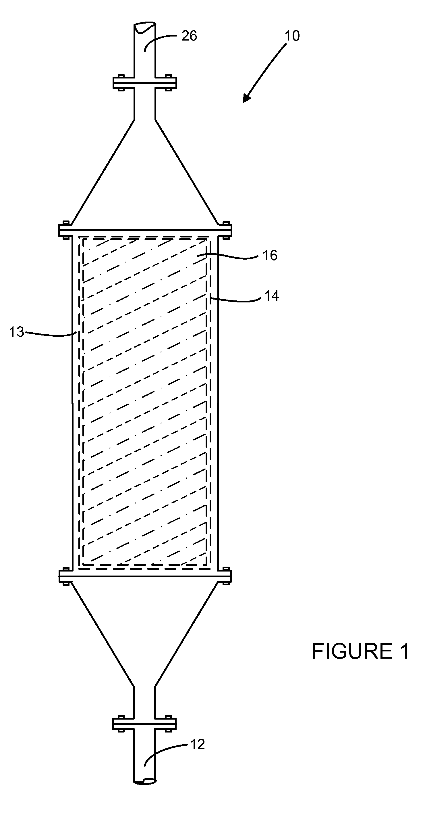
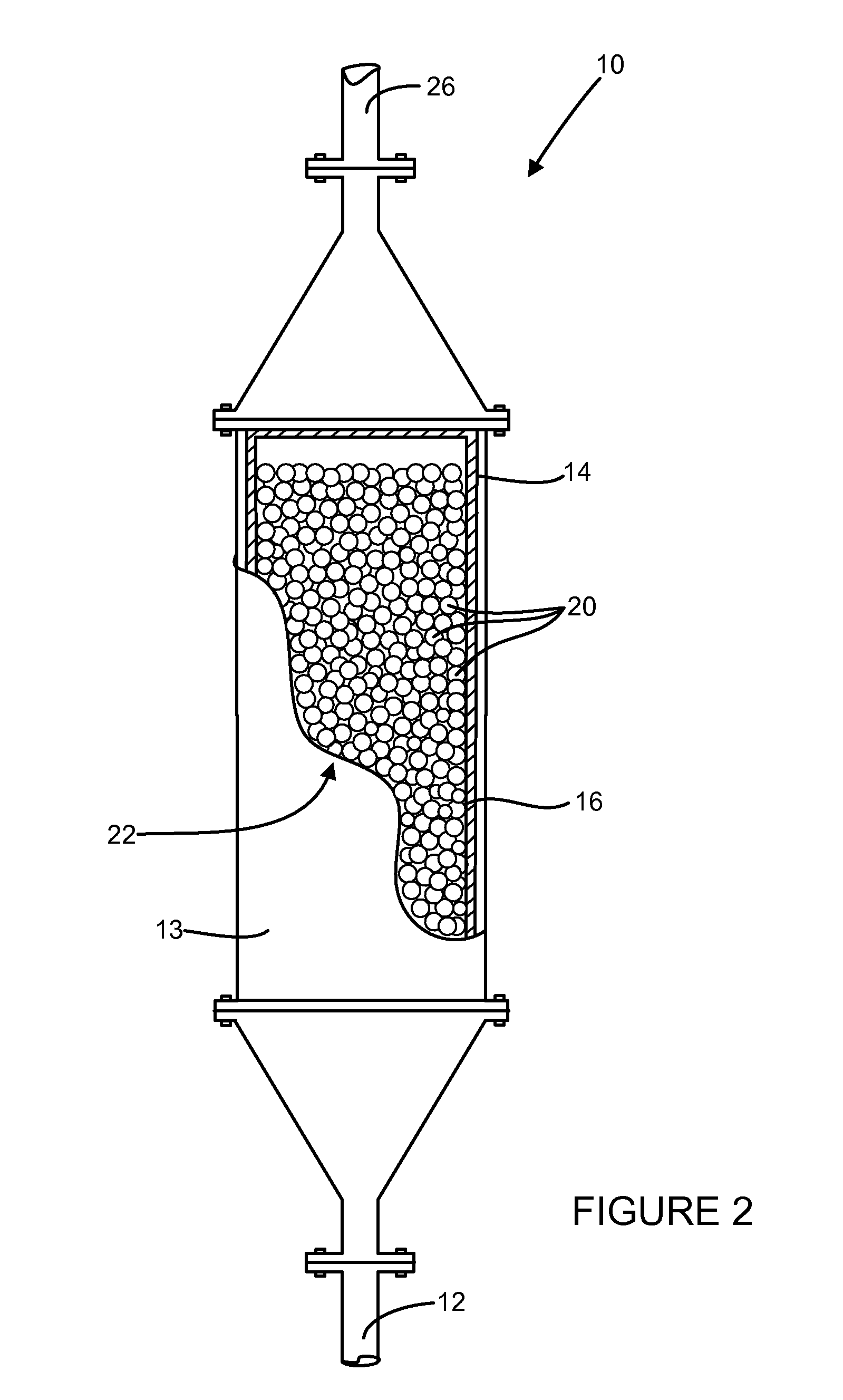
[0008]In another aspect, the disclosure provides a pollution abatement system comprising a combustion source that generates an effluent stream comprising at least one air pollutant selected from the group consisting of: sulfur oxides, nitrogen oxides, carbon dioxide that is present in the effluent stream at an initial amount. The system includes a packed bed reactor having an inlet for receiving the effluent stream and an outlet. The reactor has at least one chamber comprising a plurality of solid particles having an average particle diameter size of about 0.25 mm to about 12 mm, wherein the solid particles are formed by admixing a slag component having one or more reactive silicate compounds with a binder component. The chamber has a volume to provide a sufficient residence time to reduce an amount of the air pollutant by a removal efficiency of greater than or equal to about 20% in the effluent stream as compared to the initial amount.
[0009]In another aspect, the disclosure provides a method of reducing pollution generated by a combustion source, comprising introducing an effluent fluid stream generated in a combustion source to a packed bed reactor, where the effluent stream has a temperature of less than about 600° F. (about 316° C.). The effluent fluid stream has an initial amount of at least one air pollutant selected from the group consisting of: sulfur oxides, nitrogen oxides, and carbon dioxide, and the packed bed reactor has at least one chamber comprising a plurality of solid particles having an average particle diameter size of about 0.25 mm to about 12 mm that are formed by admixing a slag component having one or more reactive silicate compounds with a binder component. The reactor preferably operates with a removal efficiency of the air pollutant of greater than or equal to about 20%.
[0011]In various other aspects, the disclosure provides methods of reducing sulfur oxides, nitrogen oxides, and / or carbon dioxide emissions from effluent streams generated by stationary combustion sources (e.g., boilers, incinerators), cement kilns, lime kilns, iron furnaces and steel furnaces. In this manner, various aspects of the disclosure provide an effective means for removing sulfur oxides, nitrogen oxides, and / or carbon dioxide emissions, thus controlling greenhouse gas emissions, while further recycling at least one industrial byproduct, and preferably multiple byproduct materials, to form a useful product.

Problems solved by technology

Such combustion sources typically generate a variety of hazardous air pollutants, depending on the types of fuels burned, materials processed, burner design, and other operating parameters.
Many such air pollution control devices are energy intensive and require high temperatures and large capital and maintenance expense.

Method used


Image

  • Methods and devices for reducing hazardous air pollutants
  • Methods and devices for reducing hazardous air pollutants
  • Methods and devices for reducing hazardous air pollutants

Examples


example i

[0107]A solid pelletized material is formed by mixing 10% by weight of Type III (chemically and physically similar to Type I cement except ground finer to produce higher early strengths ranging from 320 to 670 m2 / g Blaine fineness, generally greater than about 450 m2 / g Blaine fineness) weight Portland cement with 90% stainless steel slag in a mixer. 30% water is added to the mixture (on a wet basis 63% slag and 7% Portland cement) until pelletized particles are formed having an average particle diameter of about 2 to 6 mm. The solid particles are placed in a packed bed reactor having a reactor bed divided into three stages. The reactor is 8 inches (about 20 cm) in diameter and has a length of about 3 feet (91 cm). The three-stage reactor bed is filled to a height of about 2.5 feet (about 76 cm). A coal-burning furnace is operated to generate an effluent having a flow rate of about 41,000 cubic feet per minute and containing sulfur oxides (SOX), nitrogen oxides (NOX), and carbon diox...


PUM

PropertyMeasurementUnit
temperatureaaaaaaaaaa
particle size diameteraaaaaaaaaa
differential pressureaaaaaaaaaa

Abstract

The disclosure provides methods and systems for sequestering and / or reducing sulfur oxides, nitrogen oxides and / or carbon dioxide present in industrial effluent fluid streams. A solid particulate material comprising a slag component, a binder component (distinct from the slag component), and optionally water is formed and then contacted with the effluent fluid stream to reduce at least one of the sulfur oxides, nitrogen oxides, and / or carbon dioxide. The contacting of the effluent stream may occur in a packed bed reactor with the solid dry particulate material. Methods of reducing pollutants from exhaust generated by combustion sources, lime and / or cement kilns, iron and / or steel furnaces, and the like are provided.

Description

CROSS-REFERENCE TO RELATED APPLICATIONS[0001]This application claims the benefit of U.S. Provisional Patent Application No. 60 / 973,632 filed on Sep. 19, 2007, the entire disclosure of which is incorporated herein by reference in its respective entirety.FIELD AND BACKGROUND[0002]The present disclosure relates to emissions abatement processes and in particular, to processes and devices that sequester air pollutants from combustion source effluent streams.[0003]The statements in this section merely provide background information related to the present disclosure and may not constitute prior art.[0004]Many industrial processes employ a combustion source during operation, including boilers, kilns, furnaces, and incinerators. Such combustion sources typically generate a variety of hazardous air pollutants, depending on the types of fuels burned, materials processed, burner design, and other operating parameters. Common hazardous air pollutants (HAPs) released by combustion sources include...

Claims


Application Information

Patent Timeline
Patent Type & Authority Patents(United States)
IPC IPC(8): B01D53/14B01D53/68B01D53/82B01D53/66B01D53/64B01D53/52B01D53/60B01D53/58B01D53/56
CPCB01D53/508B01D53/02Y02C10/08B01D53/565B01D53/62B01D2251/404B01D2253/106B01D2257/2045B01D2257/2064B01D2257/2066B01D2257/302B01D2257/404B01D2257/502B01D2257/504B01D2257/602B01D2257/708Y02C20/40Y02E20/32
Inventor COMRIE, DOUGLAS C.
Owner C QUEST TECH
Learn More