Multiple laser scanner

Active Publication Date: 2011-08-09
NEXTPAT
View PDF138 Cites 52 Cited by
  • Summary
  • Abstract
  • Description
  • Claims
  • Application Information

AI Technical Summary

Problems solved by technology

However, the introduction of multiple lasers creates ambiguity as it is often difficult or impossible to discern which laser is illuminating a pixel of a image sensing array.
Such scanning methods, however, are heat intensive, expensive, and the number of lasers used is limited by the number of different colored lasers available.
Problems arise in such scanning methods, however, because when scanning different objects, light captured at the sensing array tends to fall off.
Accordingly, it is difficult to discern whether the effect is due to the dot-dash patterned stripe or the geometry of the object.
This can result in erroneous depth determinations.
It has further been a challenge of multiple laser scanners to maintain a small, compact size while still being able to capture images of relatively large targets.

Method used


Image

  • Multiple laser scanner
  • Multiple laser scanner
  • Multiple laser scanner

Examples


Embodiment Construction

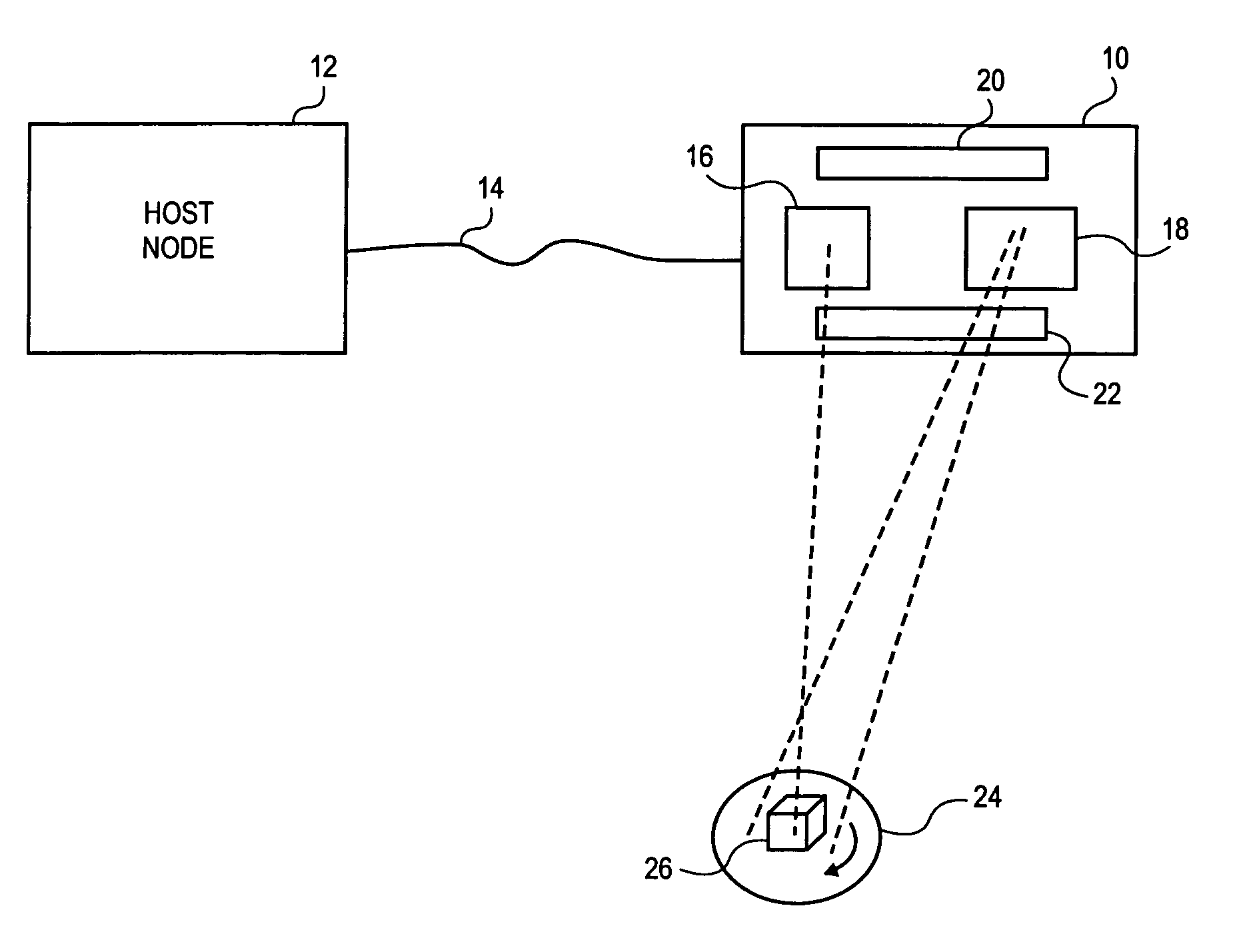
The system operates on the principal that dimension data for a three-dimensional target may be determined by disambiguating light pattern elements from multiple sources projected on the target during a scanning period. In various embodiments, the light pattern elements may be laser spots, laser stripes, or may be some other light source focused to have a discernable edge. Laser stripes may be generated by, for example, passing a laser spot through a spreading lens or by rastering the laser spot. Because of the sharp edges possible by appropriately focusing laser light, lasers have been found to be a particularly desirable source of light pattern elements.

In one embodiment, a projector having at least three lasers emitting light pattern elements (e.g., laser stripes) with unique angles between each stripe may be panned across a target object at some constant angular speed. In another embodiment, the light pattern element may be a group of stripes, a group of spots, a group of stripes...


PUM


Abstract

A method and system to capture geometry of a three dimensional target while disambiguating multiple projected target elements. The system projects at least three light pattern elements toward a target at a diverse spacing relative to each other. The system captures at least one image of the target while illuminated by at least one of the pattern elements. The pattern elements are moved relative to the target. The system disambiguates one pattern element from any other contained within an image of the target, at least in part based on the diverse spacing. The system measures triangulation locations of points on a three-dimensional surface of the target.

Description

BACKGROUND1. FieldThe invention relates to capture of three dimensional data. More specifically, the invention relates to a high speed high resolution scanner to capture three dimensional data about a target.2. BackgroundVarious scanners exist to capture geometry of three dimensional objects. One class of such scanners uses a laser to project a light pattern onto a target and then determines the dimensions of the target from the interaction of the pattern with the target. As used herein, “target” refers to all or some portion of a three dimensional object. In theory, it would be faster to scan a target using multiple lasers. However, the introduction of multiple lasers creates ambiguity as it is often difficult or impossible to discern which laser is illuminating a pixel of a image sensing array.To disambiguate multiple lasers, attempts have been made to encode the light pattern. In one such device, color is used to encode different laser stripes. In such a device, each laser emits ...

Claims


Application Information

Patent Timeline
IPC IPC(8): G06K9/00H01J3/14G01B11/30G06V10/12
CPCG01B11/245G06K9/2009G06K2209/40G06V10/12G06V2201/12
Inventor KNIGHTON, MARK S.AGABRA, DAVID S.CARDEI, VLAD CONSTANTINMILLERS, JEREMY A.FEENEY, MARK A.MCKINLEY, WILLIAM D.
Owner NEXTPAT
Why Eureka
Try Eureka